29 AIM-4SL Hardware Manual
© 2011 Apollo Security Inc.
ADA-10
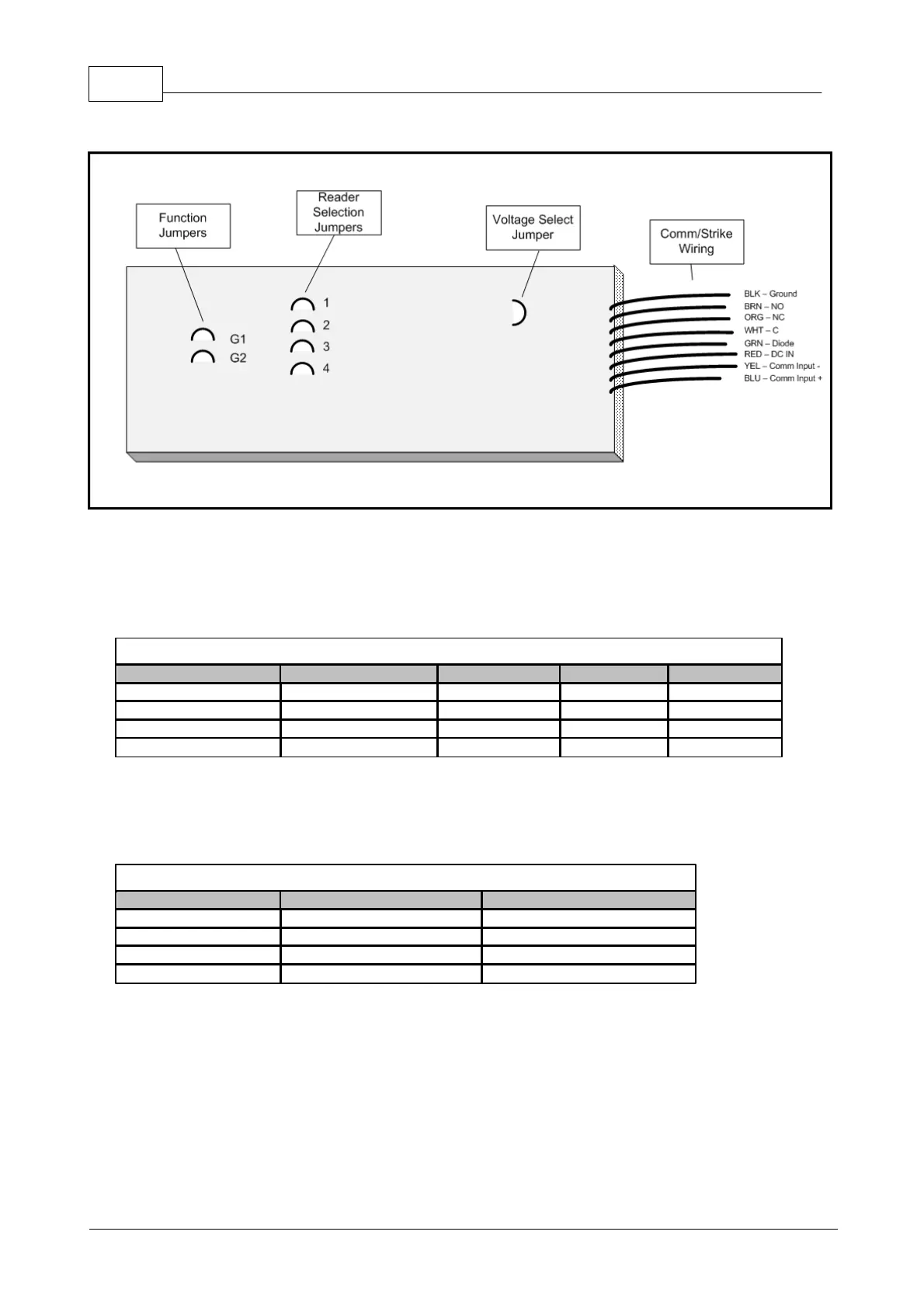
Figure 3.7.4:
ADA-10 Hardware Layout
On the ADA-10, the jumpers must be cut using wire cutters to assign the reader/function. DO NOT CUT THE
JUMPERS FLUSH WITH THE SURFACE OF THE ADA-10 AS IT MAY BE NECESSARY RECONNECT
THEM LATER IF THE WRONG JUMPERS HAVE BEEN CUT
Table 3.7.3:
ADA-10 Reader Setting
Next, the function of the ADA-10 must be defined. This is done by cutting one of the two function jumpers on
the ADA-10. For each reader, there are four possible settings:
Table 3.7.4:
ADA-10 Function Setting
The above functions will work the same for each reader. Thus, if reader 2 is selected (1=CUT, 2=NOT,
3=CUT, 4=CUT), and the function Strike Relay is selected (G1=NOT, G2=NOT), the ADA will function as the
strike relay for Reader 2.