13
CONVENTIONAL DETECTORS
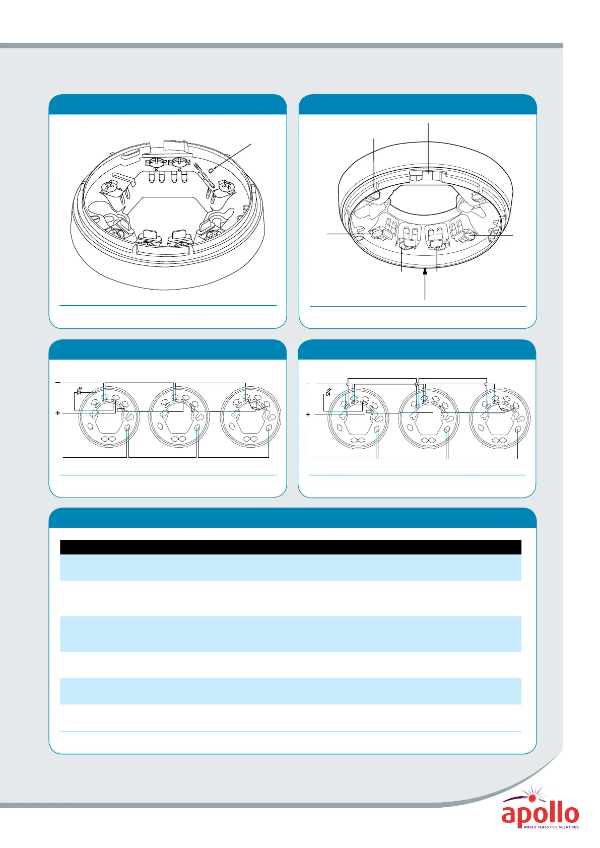
LED
—
COM
—
IN +
OUT +
Terminal 4, Screen
(Functional Earth)
Direction of LED indicated by
mark on outside of moulding
Snip along marked lines and
remove this part to lock the
detector to the base
OUT +
LED
—
IN & OUT
—
IN +
TimeSaverBase®
Figure 5
© Apollo Fire Detectors Limited 2004/JDR
© Apollo Fire Detectors Limited 2004/JDR
The lettering here
indicates the type of base
Identifying Base Marking Codes
Figure 4
© Apollo Fire Detectors Limited 2004/JDR
From
control
panel
Screen
(Functional
Earth)
From
control
panel
Screen
(Functional
Earth)
LED
—
COM
—
IN +
OUT +
1
23
4
LED
—
COM
—
IN +
OUT +
1
23
4
LED
—
COM
—
IN +
OUT +
1
23
4
LED
—
COM
—
IN +
OUT +
1
23
4
LED
—
COM
—
IN +
OUT +
1
23
4
LED
—
COM
—
IN +
OUT +
1
23
4
Base wiring diagram
Figure 6
© Apollo Fire Detectors Limited 2004/JDR
Orbis features: LED status
Table 3
Feature Description of Feature Red LED Status Yellow LED Status
StartUp™
Confirms that the detectors are wired in the correct
polarity
Flashes once per second No Flash
FasTest®
Maintenance procedure, takes just 4 seconds
to functionally test and confirm detectors are
functioning correctly
Flashes once per second No Flash
DirtAlert™
Shows that the drift compensation limit has been
reached
No Flash
Flashes once per second in
StartUp (Stops flashing when
StartUp finishes)
SensAlert® Indicates that the sensor is not operating correctly No Flash
Flashes every 4 seconds (Flashes
once per second in StartUp
Normal
Operation
At the end of StartUp and FasTest (without flashing
LED as standard)
No Flash No Flash
Flashing LED
Version
Detector’s red LED flashes in normal operation
(at the end of FasTest)
Flashes every 4 seconds No Flash
From
control
panel
Screen
(Functional
Earth)
From
control
panel
Screen
(Functional
Earth)
LED
—
COM
—
IN +
OUT +
1
23
4
LED
—
COM
—
IN +
OUT +
1
23
4
LED
—
COM
—
IN +
OUT +
1
23
4
LED
—
COM
—
IN +
OUT +
1
23
4
LED
—
COM
—
IN +
OUT +
1
23
4
LED
—
COM
—
IN +
OUT +
1
23
4
3 bases wired with a common LED
Figure 7
© Apollo Fire Detectors Limited 2004/JDR
www.acornfiresecurity.com
www.acornfiresecurity.com