3
Customer Service (704) 841-6000
backflow.apollovalves.com
ES1600 REV A.
BFMMRP4ALBF
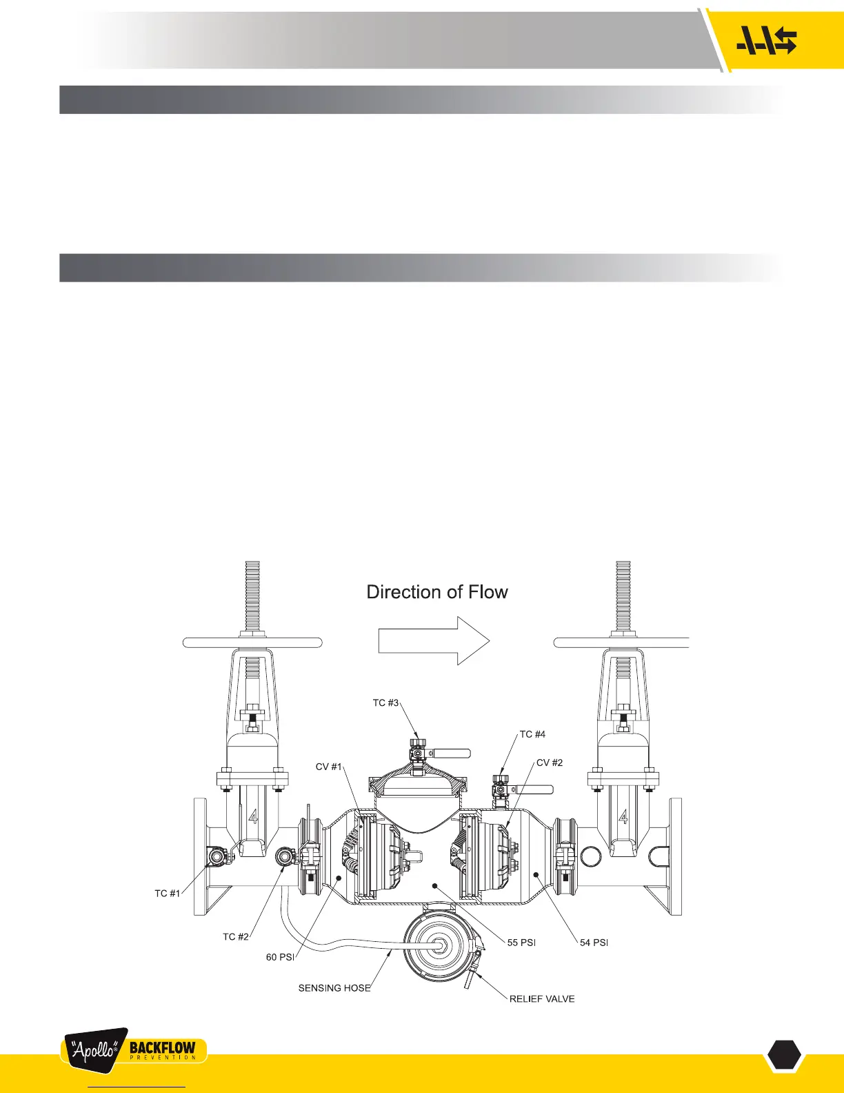
FIGURE 1
The Reduced Pressure Principle (RP) device consists of two independently-acting, spring-loaded check valves, together with a hydraulically
dependent, mechanically independent pressure differential relief valve, located in the zone between the check valves. Two resilient seated
shut-off valves and four test cocks complete the assembly.
The first check is designed to maintain a minimum of 5 psi across the check valve. The second check is designed to maintain a minimum of
1 psi across the check valve during normal operation. The relief valve operates on a differential pressure. Supply pressure on the upstream
side of the first check valve acts against the diaphragm to close the relief valve during normal operation. In the event of back-pressure, the
relief valve will open to maintain the pressure in the “zone” at least 2 psi less than the inlet pressure.
I. DESCRIPTION AND OPERATION
II. INSTALLATION
1. The RP must be installed in an accessible location to facilitate periodic field testing and maintenance.
2. The location selected should have adequate drainage for relief valve discharge. The device should never be placed where it may be submerged
in standing water.
3. Flush all upstream piping thoroughly to remove foreign matter prior to installing the device.
4. The device should be installed in the horizontal position. A clearance between the lower most portion of the device and flood grade or floor should
be provided for ease of maintenance.
5. If shut-off valves are provided separately, they must include tapped bosses for attachment of the sensing hose, the #1 test cock, and the #2 test
cock. Contact the factory for installation instructions.
6. After installing the assembly and with downstream or #2 shut-off valve closed, pressurize the device and bleed air through test cock #4. Then
open #2 shut-off valve.
OTHER INSTALLATION TIPS
• The installation location should have adequate drainage for relief valve discharge. The device should never be placed where it may be sub-
merged in standing water. Do not install in areas subject to freezing without using a properly designed enclosure.
• As in any piping system, provisions should be made to minimize water hammer and pressure rise due to thermal expansion, as these conditions
can create damaging and dangerously high internal pressures.
• A “Y” strainer can be installed just upstream of the RP assembly to eliminate any debris from entering the device and fouling the check and/or
relief valve. Note: Strainers are normally not allowed on fire protection systems. Check with local authorities.
TC: TEST COCK
CV: CHECK VALVE
Note: Pressures are for illustrative purposes only and are not necessarily indicative of any actual valve.