L1 IN
L1 OUT
L1 IN
L1 OUT
L1 IN
L1 OUT
1
4
16
64
2
8
32
128
1
4
16
64
2
8
32
128
1
4
16
64
2
8
32
128
+
-
From
previous
device
or FACP
-L1
-L1
+L2
+R
-R
-L1
-L1
-L1
+L2
+R
-R
-L1
+L2
+R
-R
+
-
To next
device
or FACP
1
4
16
64
2
8
32
128
1
4
16
64
2
8
32
128
1
4
16
64
2
8
32
128
+
-
+
-
From
previous
device
or FACP
To next
device
or FACP
L1 IN
L1 IN
L1 IN
L1 OUT
L1 OUT
L1 OUT
-L1
-L1
+L2
+R
-
R
-L1
-L1
-L1
+L2
+R
-R
-L1
+L2
+R
-R
L1 IN
L1 OUT
L1 IN
L1 OUT
L1 IN
L1 OUT
1
4
16
64
2
8
32
128
1
4
16
64
2
8
32
128
1
4
16
64
2
8
32
128
+
-
From
previous
device
or FACP
-L1
-L1
+L2
+R
-R
-L1
-L1
-L1
+L2
+R
-R
-L1
+L2
+R
-R
+
-
To next
device
or FACP
32
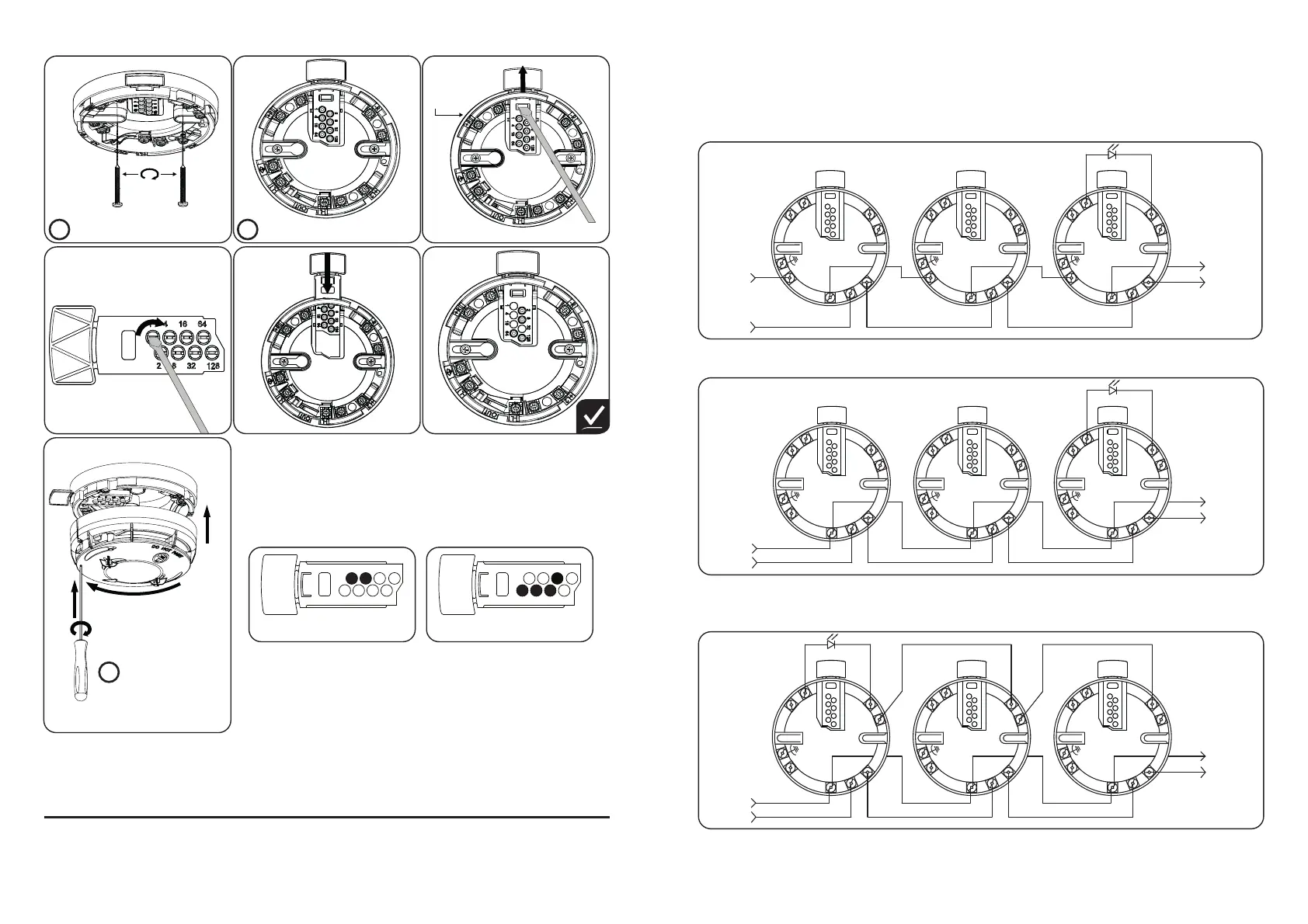
Fig. 3 Schematic Wiring Diagram: Soteria UL Base to bypass isolator with a Common
Remote LED. To be used in a retrofi t application for the older version of XP95A or
Discovery UL product. Can also be used when the isolator feature is not required
Fig. 2 Schematic Wiring Diagram: Soteria UL Base Detector to bypass isolator with remote
LED connection. To be used in a retrofi t application for the older version of XP95A or
Discovery UL product. Can also be used when the isolator feature is not required
XPERT 8 Card Addressing
Select the desired address and remove the pips indicated
in black.
To reach maximum address range use Soteria UL Bases with
XPERT 8 card, Soteria Detector and Core Protocol Control
Panel.
Wiring
CAUTION: Do not use looped wire under wiring terminals. Break wire run to provide
supervision of connections. Terminals L1 and L2 are polarity sensitive. It is recommended the
wiring be no smaller than 18AWG (0.8mm
2
). Wire sizes up to 14 AWG (3.3mm
2
) may be used.
Warning: Check the base compatibility before installing
Check the polarity for Soteria UL detector installation
Fig. 1 Schematic Wiring Diagram: Soteria UL Base wiring with remote LED connection. To be
used with new installs for XP95A and Soteria UL detectors
4
5
6
Installation Diagram
2
For wiring, please see Fig 1, 2 & 3
i
Do Not
Overtighten
Screws
1
Screws not provided
i
3
Further details of XPERT 8 addressing can be found in the
Apollo Fire App, please refer to https://www.apollo-fi re.
co.uk/training-support/apollo-mobile-app
For further technical information please refer to Technical
Bulletin 39215-400 Issue 1.
7
1.5mm A/F Hex
Grub Screw for use
as anti-tamper /
locking mechanism
i
53
1
41664
2 8 32 128
1 + 4 + 16 + 32 = 53
10
1
41664
2 8 32 128
2 + 8 = 10
© Apollo Fire Detectors Ltd 2021
Apollo Fire Detectors Ltd,
36 Brookside Road, Havant, Hampshire, PO9 1JR, UK
Tel +44 (0)23 9249 2412 e-mail: techsales@apollo-fi re.com
Website: www.apollo-fi re.co.uk
In the USA: Apollo America Inc.,
30 Corporate Drive, Auburn Hills, Michigan, 48326, USA
Tel: (248) 332-3900 Fax: (248) 692-0888
e-mail: info.us@apollo-fi re.com
Website: www.apollo-fi re.com
 Loading...