2
Symbols in this Manual.
This symbol indicates where cautionary or other information is found in the manual.
= Battery
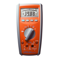
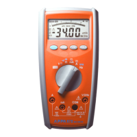
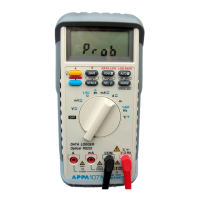
1-3 Front Panel
Refer to Figure 1 and the following numbered steps to familiarize yourself with the meter’s front panel controls
and connectors.
1. Digital Display — The digital display has a 3 3/4 digit LCD readout (maximum reading 3999) plus decimal
point , AC, DC, AUTO , HOLD , MAX ,
<and unit annunciators.
2. Input Terminal — The black test leads is always connected to the “COM” input terminal and red test lead is
always connected to the “V-Ω” input terminal when measuring ACV or DCV or RESISTOR or CONTINUITY.
3. Function Switch — This slide switch is used to select V , V, A , A , Ω ,
< function.