19
3-5 Continuity Check by Buzzer
1. Connect the red test lead to the “VΩHz” terminal and the other (black) test lead to the “COM” terminal.
2. Set the rotary function selector to “Ω : ” position.
3. Connect the test leads to the circuit to be measured. The buzzer will sound if the resistance of the circuit
measured is lower than 30Ω approximately.
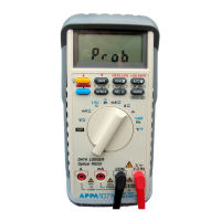
3-6 Diode Check
1. Set the rotary switch at “Ω : ” position.
2. Connect black test lead to “COM” terminal and red lead to “ VΩHz ” input terminal.
3. Connect test leads to the diode. Normally the forward voltage drop of good silicon diode is shown between.
0.400V to 0.900V. If the diode under test is defective, “000” (short circuit) or “OL” (non-conductance) is
displayed. During reverse checking the diode is normal if “OL” is displayed, “000” or other values are displayed
if it is defective.