8
7
2
10
12
14
13
5
3
1
6
9
SPECIFICATIONS
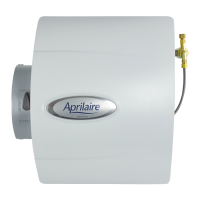
Humidier Dimensions:
Width (including solenoid valve): 15-3/8”
Height (including drain spud): 15-3/4”
Depth: 10-1/4”
Bypass Duct Opening: 6” diameter
Plenum Opening: 10”W x 12-3/4”H
Water Feed Rate: 3 gph
Electrical Data: 24 VAC, 60 Hz, 0.5 Amp
Water Panel®: Model 45
INSTALLATION OPTIONS (LEFT HAND DISCHARGE SHOWN)
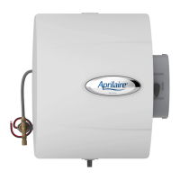
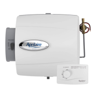
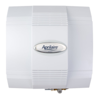
AprilAire Model 400 and 400M can be installed on either the supply plenum or cold air return of a forced air handling
system with right hand or left hand bypass duct connections. The humidier dimensions and serviceability must be
considered when selecting the best location for the humidier.
The humidier functions with cold, hot, softened, or unsoftened water.
FURNISHED ITEMS
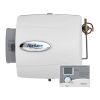
• Humidier with built-in bypass damper
• 24 VAC transformer
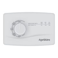
• Automatic Digital Humidier Control
and Outdoor Temperature Sensor
(Model 400 only)
• Manual Humidier Control
(Model 400M only)
• Humidier Control Installation Instructions
• Saddle valve
• Humidier Installation Template
ITEMS NOT FURNISHED
• Mounting screws
(sheet metal screws)
• Water supply line
(1/4” O.D. copper)
• Overow tube
(1/2” I.D. hose)
• Low voltage wire
(18-22 gauge)
• Bypass ductwork
• Model 50 current sensing
relay (if required)
PARTS LIST
5. Water Panel
6. Scale Control
Insert/Float
Chamber
7. Bypass
Damper
8. Damper
Handle
9. Water Level
Sensor
Assembly
10. Hole Plug
11. Nameplate
12. Solenoid Valve
13. Float
14. Float Cover
1. Front Cover
2. Base
3. Feed Tube
4. Water
Distribution
Tray
RETURN
FLOOR DRAIN OR
CONDENSATE
PUMP
OVERFLOW TUBE
FLOOR DRAIN OR
CONDENSATE
PUMP
RETURN
SUPPLY
SUPPLY
FLOOR DRAIN OR
CONDENSATE
PUMP
OVERFLOW TUBE
OVERFLOW TUBE
FLOOR DRAIN OR
CONDENSATE
PUMP
HORIZONTALUPFLOW
90-1079
400 Series
Water Saver
Evaporative HumidierHumidier
Product Info &
Digital Manual
TEMPLATE MUST BE LEVEL
90-1263
INSTALLATION TEMPLATE
WARNING
• ATTENTION INSTALLER: Read this manual before
installing. Improper installation or maintenance
may cause property damage or injury. It is
recommended that installation, service, and
maintenance be performed by a trained service
technician. This product must be installed in
compliance with all local, state, and federal codes.
• ELECTRIC SHOCK HAZARD: 120 volts may cause
serious injury from electric shock. Disconnect
electrical power to the HVAC system and
humidier before starting installation or servicing.
Leave power disconnected until installation/
service is completed.
• RISK OF SCALDING. Water temperature over 125°F
can cause severe burns and scald instantly. Shut
off the hot water supply before disconnecting or
tapping into any hot water supply line.
• Avoid obstructions such as plumbing or electrical
wires when cutting into walls.
CAUTION
• SHARP EDGES MAY CAUSE INJURY FROM CUTS. Use
care when cutting plenum openings and handling
ductwork. Always wear glasses/goggles and
gloves when installing the unit.
• Dropping may cause personal injury or equipment
damage. Handle with care and follow installation
instructions.
NOTICE
FREEZING TEMPERATURES CAN BURST WATER PIPES.
• Do not install the humidier where freezing may
occur. The water line could freeze and crack
causing water damage to the home.
CONDENSATION DAMAGE OR MOLD CAN OCCUR.
• Position the return duct mounted humidier
control at least 6” upstream of the humidier,
bypass duct connection, or fresh air intake for
accurate humidity sensing.
• Position the wall-mounted humidier control in
areas unaffected by drafts or heat sources for
accurate humidity sensing.
• Lower the humidity setting on the humidier
control if there is excess condensation on the
inside of any windows in unheated living spaces.
EQUIPMENT DAMAGE MAY OCCUR IF INSTALLATION
INSTRUCTIONS ARE NOT FOLLOWED.
• Do not install the humidier or bypass connection
on the furnace jacket.
• Do not connect the transformer to the blower
motor wiring.
• Do not install the humidier or bypass connection
on a plenum face at the blanked end of the
cooling coil.
• If water pressure exceeds 125 psi, reduce water
pressure with devices allowed by local codes.
• Use water with a temperature no greater than
140°F (60°C).
• Do not install the humidier on systems with
differential pressure greater than 0.4” w.c. between
the supply and return plenums.
• When installing the humidier control on the
return duct of a downow furnace, ensure blower
continues to run after a heat call is satised to
eliminate high temperatures from damaging the
humidier control.
• Periodically check drain line to make sure water
ows freely to drain.