EasyManua.ls Logo

Aprilaire 500M - User Manual

Aprilaire 500M
2 pages
Print Icon
To Next Page IconTo Next Page
Loading...
FURNACE
BLOWER MOTOR
MODEL 50
CURRENT
SENSING RELAY
(IF REQUIRED)
24 VAC FURNACE
ACCESSORY TERMINALS
OR TRANSFORMER
(10VA MINIMUM)
SHUT-OFF
(SADDLE VALVE)
WATER SUPPLY
YELLOW 24V
SOLENOID
VALVE WIRES
IMPORTANT
USE 120 VAC POWER SOURCE OTHER THAN FURNACE MOTOR
CIRCUIT. HOWEVER, THE TRANSFORMER CAN BE POWERED
OFF THE HOT 120 VAC LINE BEFORE IT ENTERS THE FURNACE.
DO NOT WIRE TRANSFORMER INTO FURNACE BLOWER CIRCUIT.
IMPORTANT
WHEN MODEL 50 CURRENT SENSING RELAY IS USED:
WIRE MODEL 50 CURRENT SENSING RELAY INTO
24 VAC HUMIDIFIER CONTROL CIRCUIT ONLY!
DO NOT INSTALL IN TRANSFORMER PRIMARY CIRCUIT.
CONNECT DRAIN LINE HERE
COMMON
HI
LO
WATER SUPPLY
COMMON
24 VAC FURNACE
ACCESSORY TERMINAL
CONTINUOUSLY POWERED
24 VAC TRANSFORMER
PROVIDED WITH HUMIDIFIER
SHUT-OFF
(SADDLE VALVE)
YELLOW 24V
SOLENOID
VALVE WIRES
IMPORTANT
DO NOT WIRE TRANSFORMER
INTO FURNACE BLOWER CIRCUIT.
NORTH, EAST
OR WEST SIDE
OF HOME
R C A B ODT CfW/G H
CONNECT DRAIN LINE HERE
ABOVE EXPECTED
SNOW LINE
NOTE: IF 120V, INSTALL 24V TRANSFORMER.
24V ACTIVATED WITH HEAT CALL.
TERMINALS MAY BE LABELED: “HUM”, “ACC” OR “EAC”
CONSULT FURNACE MANUFACTURER FOR VOLTAGE AND
OPERATION PARAMETERS OF ACCESSORY TERMINALS.
NOTE: SEE CONTROL INSTRUCTIONS FOR OTHER
WIRING OPTIONS.
OUTDOOR
TEMPERATURE
SENSOR OR
MANUAL MODE
RESISTOR
READ COMPLETE SAFETY INSTRUCTIONS AND INSTALLATION TEMPLATE BEFORE STARTING
This product must be installed by a qualified heating and air conditioning contractor. Failure to do so could result in serious injury from electrical shock.
This product must be installed in compliance with all local, state and federal codes.
ATTENTION INSTALLER:
SMALL BYPASS HUMIDIFIER MODEL 500M AND 500A
The Model 500M and 500A Aprilaire can be
installed on either the supply or return
plenum of a forced air handling system and
is easily reversible for installation with
right hand or left hand bypass duct
connections. The humidifier dimensions
and serviceability must be considered
when selecting the best location for the
humidifier. Here are 2 examples of many
types of installations.
RESEARCH PRODUCTS CORPORATION • P.O. BOX 1467 • MADISON, WI 53701-1467 • CALL 800/334-6011 • FAX 608/257-4357
RETURN
SUPPLY
RETURN
SUPPLY
Horizontal
Upflow
90-1207
90-1204
90-1079
WARNING
1. ELECTRICAL SHOCK HAZARD.
Disconnect electrical power to the
furnace before starting installation.
Failure to do so could result in
serious injury from electrical shock.
2.
SHARP EDGES HAZARD. Sharp
edges may cause serious injury from
cuts. Use care when making plenum
openings and handling ductwork.
3.
RISK OF SCALDING. Water
temperature over 125°F can cause
severe burns and scald instantly.
Shut off the hot water supply before
disconnecting or tapping into any
hot water supply line.
SPECIFICATIONS
HUMIDIFIER DIMENSIONS
Width (including solenoid valve): 15
5
8Ó
Height
(including drain spud): 13
Depth
: 10
1
4
BYPASS DUCT OPENING
6 diameter
PLENUM OPENING
9
1
2W x 9
1
2H
WATER FEED RATE
3 gph
ELECTRICAL DATA
24 VAC-60 Hz, 0.5 AMP
CAUTION
1. Do not install humidifier where freezing temperatures
could occur. The water line could freeze and crack
causing water damage to the home.
2. Do not install humidifier or bypass connection on the
furnace jacket.
3. Do not install humidifier or bypass connection on a
plenum face where the blanked off ends of the cooling
coil will restrict air movement through the humidifier.
4. Do not set humidity level above recommended or to
recommended level if condensation exists on inside
windows of any unheated space, as condensation
damage may result. Excess humidity can cause
moisture accumulation which can allow the possibility
for mold growth in the home.
5. Do not connect Model 500M or 500A
transformer to blower motor wiring.
Premature component failure may result.
6. When installing Humidifier Control on downflow
furnace, ensure blower continues to run after a
heat call is satisfied to eliminate high temperatures
from damaging the Humidifier Control.
7. Do not install humidifier where water pressure
exceeds 125 psi, since damage to the humidifier
may result. Follow codes in effect concerning
pressure reduction.
8. Do not install humidifier on systems with
greater than 0.4 in. wg pressure differential
between supply and return plenums.
RISK OF PROPERTY AND EQUIPMENT DAMAGE.
INSTALLATION OPTIONSRECOMMENDED WIRING DIAGRAMS
(SEE STEP 7 ON BACK AND “HUMIDIFIER CONTROL SAFETY AND INSTALLATION INSTRUCTIONS” FOR DETAILED WIRING INSTRUCTIONS)
Model 500M
MANUAL CONTROL
Model 500A
AUTOMATIC DIGITAL
HUMIDIFIER CONTROL
NOTE
When installing Aprilaire humidifier
on a heat pump system, use hot
water. The heated water supplements
the reduced supply air temperature
as added heat for evaporation.
For Aprilaire Humidifier Parts Drawing 2007, click here.
The current Model 500 is identical to the previous Model 500A (except the 500A came with a 2nd spare water panel).
Question and Answer IconNeed help?

Do you have a question about the Aprilaire 500M and is the answer not in the manual?

Summary

ATTENTION INSTALLER

General Safety Warnings

Crucial safety precautions for electrical shock, sharp edges, and scalding hazards.

CAUTION

Risk of Property and Equipment Damage

Precautions to prevent freezing, damage to furnace, moisture issues, and electrical/pressure problems.

SPECIFICATIONS

Technical Specifications Summary

Details humidifier dimensions, duct opening sizes, water feed rate, and electrical data.

RECOMMENDED WIRING DIAGRAMS

Model 500 M Manual Control Wiring

Wiring diagram for the Model 500M manual control, including 120 VAC power source.

Model 500 A Automatic Digital Humidifier Control Wiring

Wiring diagram for the Model 500A automatic control, using 24 VAC furnace accessory terminals.

INSTALLATION OPTIONS

Installation Configuration Examples

Illustrates common installation configurations for upflow and horizontal systems.

Installation Steps

Furnished and Not Furnished Items

Lists items included with the humidifier and items that must be supplied separately.

Step-by-Step Installation Procedure

Details the process from removing the cover to securing the humidifier base and cutting openings.

Bypass Duct Connection

Instructions for positioning the bypass duct and attaching it to the humidifier collar.

Control Installation and Wiring

Guidance on wiring the humidifier control, emphasizing disconnecting furnace power first.

Water Supply and Drain Lines

Instructions for connecting the water supply via saddle valve and the drain line to a floor drain.

Operation Check and Finalization

Steps to check humidifier operation, ensure connections are watertight, and set the control properly.

Overview

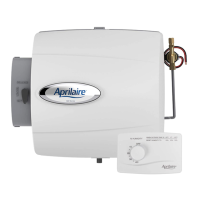
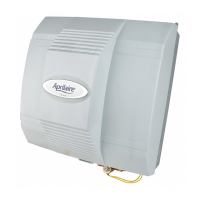
The Aprilaire Model 500M and 500A are small bypass humidifiers designed to integrate with forced air heating and air conditioning systems to maintain optimal humidity levels in a home. These devices are intended for installation by qualified heating and air conditioning contractors to ensure proper function and safety. The primary function of the humidifier is to add moisture to the air, which can improve comfort and help protect wood furnishings and other household items from drying out in arid conditions.

Function Description:

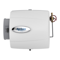
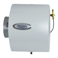
The core mechanism involves a Water Panel® Evaporator, which is a porous pad that absorbs water. As air from the furnace's supply or return plenum passes through the humidifier, it flows over the wetted Water Panel®, picking up moisture through evaporation. A solenoid valve controls the water flow to the distribution tray, ensuring the Water Panel® remains saturated. Excess water drains away, preventing mineral buildup on the panel and maintaining efficiency. The humidifier includes a bypass damper that directs a portion of the system's airflow through the humidifier during the heating season (WINTER setting) and can be closed during the cooling season (SUMMER setting) to prevent humidification when not desired.

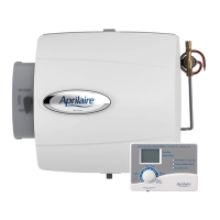
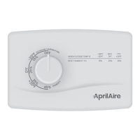
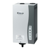
The Model 500M features a manual humidifier control, allowing the homeowner to set the desired humidity level directly. This control can be mounted on a return duct or on a wall in the living space, offering flexibility in placement. The Model 500A, on the other hand, incorporates an automatic digital humidifier control. This more advanced control continuously monitors the indoor humidity and, in some configurations, the outdoor temperature, to automatically adjust the humidifier's operation and maintain a consistent, comfortable humidity level without constant manual intervention. Both models require a 24 VAC power source, typically provided by a transformer included with the humidifier, and are designed to operate in conjunction with the furnace's heat call to ensure humidification only occurs when the heating system is active.

Usage Features:

The Aprilaire humidifiers are designed for ease of use once installed. For the Model 500M, users simply adjust a knob on the manual control to increase or decrease the desired humidity level. The Model 500A's digital control offers a more sophisticated experience, often with a display that shows current humidity and settings, allowing for precise control and automatic operation. The bypass damper, which is integral to the humidifier, can be easily switched between "WINTER" and "SUMMER" settings by the homeowner, optimizing performance for different seasons.

The humidifiers are versatile in terms of water supply, capable of functioning with cold, hot, softened, or unsoftened water. Using hot water (up to 140°F) is recommended, especially with heat pump systems, as it enhances evaporative capacity, supplementing the reduced supply air temperature for more efficient humidification. The saddle valve provided for water supply connection is designed for full open or closed operation, not for flow regulation. The design allows for installation on either the supply or return plenum and is reversible for right-hand or left-hand bypass duct connections, providing flexibility to fit various HVAC system configurations.

Maintenance Features:

Maintenance for the Aprilaire humidifiers is straightforward and designed to be user-friendly. The primary maintenance task involves replacing the Water Panel® Evaporator. The humidifier's cover can be easily removed by pressing top and bottom tabs, allowing access to the internal components. The feed tube can then be pulled out, and the Water Panel® Evaporator assembly can be removed and replaced. The scale control insert, located at the bottom of the evaporator assembly, helps manage mineral buildup and should be checked during Water Panel® replacement.

The design emphasizes accessibility for servicing. The drain spud and cap can be swapped for right-side or left-side bypass configurations, and the nameplate can be rotated if necessary for proper orientation. The continuous draining of excess water helps to flush away mineral deposits, reducing the frequency of deep cleaning required for the unit itself. The installation instructions emphasize ensuring all plumbing connections are watertight and all electrical connections are secure to prevent issues. The owner's manual, which includes instructions for operation and warranty information, is crucial for homeowners to understand proper usage and maintenance, thereby avoiding unnecessary service calls and ensuring the longevity of the humidifier. Regular checks of the humidifier's operation, especially at the beginning of the heating season, are recommended to confirm proper function and optimal humidity delivery.

Aprilaire 500M Specifications

General IconGeneral
TypeBypass
Control TypeManual
Voltage24V
InstallationProfessional installation recommended
Warranty5-year limited warranty
Coverage AreaUp to 3, 000 sq. ft.
Mounting LocationHVAC Duct

Related product manuals