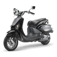
Do you have a question about the APRILIA HABANA 125 - PART3 and is the answer not in the manual?
| Fuel System | Carburetor |
|---|---|
| Front Brake | Disc |
| Rear Brake | Drum |
| Engine | Single cylinder, 4-stroke |
| Cooling | Air |
| Transmission | Automatic |
Check rear brake shoes after first 500 km and every 4000 km.
Have rear brake shoe wear checked by dealer after 1000 km and every 6000 km.
Verify rear brake shoe wear using the indicator and reference teeth.
If adjuster is fully screwed, shoes are worn; contact dealer.
Check tightening of suspension components and articulation functionality.
Inspect suspension after first 500/1000 km and every 4000/6000 km.
Contact dealer for operational irregularities or if technician help is needed.
Position vehicle, prepare support, check steering slack by shaking fork.
Ensure vehicle is stable when checking steering. Do not shake fork excessively.
If considerable slack is found, contact dealer for optimal steering conditions.
Periodically check slack in engine pin bushings by shaking the wheel.
If slack is noticed, contact dealer for optimal operating conditions.
Steps to remove front cover, including screws, couplings, and grille.
Handle plastic and painted components with care to avoid damage.
Steps to remove lower handlebar cover, including screws.
Handle plastic and painted components with care to avoid damage.
Steps to remove headlight metal ring, including screw.
Steps for partial removal, including mirrors, rubber ring, and coupling.
Handle carefully, do not force electric wires, proceed with care.
Steps to remove rear-view mirrors, including nut and washer.
Steps to partially remove dashboard, including nuts and screws.
Steps to reach dashboard bulbs by removing covers and elements.
Steps to remove central inspection cover, including screw.
Handle painted components with care to avoid scraping or damaging them.
Steps to remove right/left inspection covers, including screws and saddle lift.
Handle plastic and painted components with care to avoid damage.
Steps to remove battery cover, including saddle lift and screw.
Check stand rotation and spring condition. Grease joint if necessary.
Side stand automatically retracts when vehicle is straightened. Beware of falling.
Vehicle has stoplight switches on rear and front brake levers.
Check switches for dirt, ensure pin movement, and cable connections.
Adjust idling after first 500/1000 km and whenever irregular.
Warm engine, connect rev counter, adjust idling speed using specified controls.
Ensure proper ventilation when engine is running during adjustment.
Act on adjusting screw (1) on the carburetor for H50/HC50.
Act on adjusting knob (2) for H125/HC125; clockwise increases RPM.
Ideal slack of accelerator control should be about 2-3 mm.
Adjust slack by loosening nut, acting on adjuster, and tightening nut.
Ensure handlebar rotation doesn't affect idling and throttle returns smoothly.
Check spark plug after first 500/1000 km; change every 4000/6000 km.
Periodically clean spark plug, removing carbon deposits; change if necessary.
Steps to access spark plug by removing inspection covers.
Remove cap, clean area, unscrew plug, extract carefully.
Check spark plug gap (0.6-0.7mm H50/HC50, 0.7-0.8mm H125/HC125). Adjust if needed.
Tighten spark plug by hand, then with tool kit. Specific torque values provided.
Ensure spark plug is well tightened to prevent engine overheating and damage.
Keep flammable substances away from electrical components. Risk of fire.
Never invert battery cable connections; connect positive first, then negative.
Check electrolyte level and terminal tightening after first 500 km and every 4000 km.
Electrolyte is toxic and caustic; wear protection. Handle with care.
H125/HC125 has a maintenance-free battery; only occasional checks/recharge needed.
Recharge battery if unused for >15 days to prevent sulphation. Check charge monthly.
Ensure terminals are in good condition, not corroded, and covered with grease.
Disconnect battery, clean terminals with wire brush, reconnect, and grease.
Remove battery cover, disconnect cables, remove breather pipe, and extract battery.
Store removed battery in a safe place away from children.
Position vehicle, wait for cooling, ensure ignition off, release belt, move battery.
Do not force cables while removing battery.
Disconnect negative then positive cables, position battery safely.
Check fluid level between MIN and MAX marks. Top up with distilled water if needed.
Remove battery, check electrolyte, connect charger, recharge at 1/10th capacity.
Wait 5-10 minutes after disconnecting charger before reassembly.
Install battery, connect breather pipe, connect cables (positive then negative), cover terminals.
Guide electric cables correctly during reassembly to avoid crushing.
Use only recommended fuses. Unsuitable fuses can cause damage or fire.
Turn ignition off, remove covers, extract fuses, check filament, replace if blown.
Frequent blown fuses indicate short circuit or overload; consult dealer.
Details fuse functions and ratings for H50/HC50 and H125/HC125 models.
Check beam direction by placing vehicle 10m from a wall, verify height.
Adjust beam upwards/downwards using screw (1) with a screwdriver.
Adjust inclination by loosening nut (2), adjusting headlight (3), and tightening nut.
Keep flammable substances away from electrical components. Risk of fire.
Ensure bulb cools, use gloves, avoid fingerprints, do not force wires.
Headlight contains parking light bulb (1) and low/high beam bulb (2).
Remove lower handlebar cover and protection element (3) to access bulbs.
Grasp socket (4), pull, remove bulb (1), replace with new one.
Rotate bulb socket (5) anticlockwise, press bulb (2), rotate anticlockwise, extract.
Headlight contains parking light bulb (1) and low/high beam bulb (2) (halogen).
Remove headlight metal ring and protection element (3) to access bulbs.
Grasp socket (4), pull, remove bulb (1), replace with new one.
Disconnect connector (5), release clip (7), extract bulb (6).
Headlight contains parking light bulb (1) and low/high beam bulb (2).
Remove headlight metal ring and partially remove reflector (3) to access bulbs.
Grasp socket (4), pull, remove bulb (1), replace with new one.
Rotate bulb socket (5) anticlockwise, press bulb (2), rotate anticlockwise, extract.
Headlight contains parking light bulb (1) and low/high beam bulb (2) (halogen).
Remove headlight metal ring and partially remove reflector (3) to access bulbs.
Grasp socket (4), pull, remove bulb (1), replace with new one.
Disconnect connector (5), release clip (7), extract bulb (6).
Check fuses before changing bulbs.
Remove screws, screen, ring, colored screen, and press bulb to extract.
Check fuses before changing dashboard bulbs.
Lists warning light bulbs and lighting bulbs by position and color.
Partially remove upper handlebar cover, extract bulb sockets carefully.
Remove lower handlebar cover, extract dashboard bulb sockets carefully.
Check fuses before changing dashboard bulbs.
Lists warning light bulbs and lighting bulbs by position and color.
Partially remove dashboard, extract bulb sockets carefully.
Extract dashboard bulb sockets carefully for light decrease.
Check fuse and stoplight switches before changing rear light bulb.
Remove screws, screen, press bulb, rotate anticlockwise, and extract.
Remove screw, light unit, grasp bulb socket, pull, and remove bulb.
Do not pull electric wires to extract the bulb socket.
Empty fuel tank and carburetor. Keep vehicle vertical and anchored.
Ensure vehicle is vertical and anchored to prevent leaks. Do not tow if failed.
Risk of fire. Fuel vapours are noxious. Do not smoke or use flames.
Position vehicle, stop engine, prepare container, remove fillercap, empty tank.
Remove inspection cover, insert pipe into receptacle, loosen drain screw, drain fuel.
Tighten drain screw carefully to avoid fuel leakages during refuelling.
Braking may be impaired after washing. Brake repeatedly to restore.
Clean frequently in polluted areas, high salinity/humidity, or after winter chemical use.
Use low-pressure water jet, soft sponge with shampoo, rinse, and dry with chamois.
Avoid high pressure jets on specific parts. Use water/mild soap for rubber/plastic.
Empty fuel/carburettor, extract spark plug, add oil, remove battery, wash, polish, inflate.
Store in unheated, not-humid room, away from sunlight, with minimal temperature variations.
Uncover, clean, check battery, refuel, perform preliminary checks.
Have a test ride at moderate speed in a low-traffic area after inactivity.
Provides vehicle dimensions like length, width, height, and seat height.
Details engine type, displacement, bore/stroke, compression, starting, clutch, etc.
Information on speed change gear, primary and secondary transmission.
Details fuel, oil capacities, seats, and maximum load limits.
Details frame type, front/rear suspension stroke.
Specifications for brakes, wheels, tire inflation, and ignition type.
Details spark plug type, gap, idle rpm, battery, fuses, and generator specs.
Lists bulb wattages and warning light indicators for various functions.
Recommended transmission oil (F.C., SAE 75W-90) and 2-stroke oil (GREEN HIT 2).
Recommended fork oil (F.A. 5W/20W) and grease for bearings (AUTOGREASE MP).
Neutral grease or vaseline for battery poles; CHAIN SPRAY for chains.
Recommended brake fluid is F.F., DOT 5 (DOT 4 compatible). Use new fluid only.
Recommended engine oil (EXTRA RAID 4 SAE 15W/50) and transmission oil (F.C., SAE 75W-90).
Recommended fork oil (F.A. 5W/20W) and grease for bearings (AUTOGREASE MP).
Neutral grease or vaseline for battery poles; CHAIN SPRAY for chains.
Recommended brake fluid is F.F., DOT 5 (DOT 4 compatible). Use new fluid only.
Always ask for genuine spare parts from Aprilia.
Always ask for genuine spare parts from Aprilia.
Italian headquarters contact information for Aprilia s.p.a.
Contact details for Aprilia importers in various European countries.
Contact details for Aprilia importers in countries outside Europe.
Electrical wiring diagram for the Habana 50 model.
Key for identifying components in the Habana 50 wiring diagram.
List of cable colours and their corresponding meanings for Habana 50.
Electrical wiring diagram for the Habana 50 USA model.
Key for identifying components in the Habana 50 USA wiring diagram.
List of cable colours and their corresponding meanings for Habana 50 USA.
Electrical wiring diagram for the Habana Custom 50 model.
Key for identifying components in the Habana Custom 50 wiring diagram.
List of cable colours and their corresponding meanings for Habana Custom 50.
Electrical wiring diagram for the Habana 125 model.
Key for identifying components in the Habana 125 wiring diagram.
List of cable colours and their corresponding meanings for Habana 125.
Electrical wiring diagram for the Habana Custom 125 model.
Key for identifying components in the Habana Custom 125 wiring diagram.
List of cable colours and their corresponding meanings for Habana Custom 125.
Thanks customers, advises on environmental responsibility, noise, and nature respect.



 Loading...