- 26 -
English
Settings
1 Partial opening
2 Break-in
3 Master-Slave
4 Closing speed
5 Photocell
6
Continuation during power failure
7
Last operation during power failure
8 Exit only electric lock
9 Emergency
10 N.L. mode power failure
11
N.L. mode STOP input
12
not active
fixed adaptive
free resists
M/S enabled M/S disabled
75% opening speed equal to opening speed*
N.O. N.C.
enabled disabled
closes opens
disabled enabled for every closing op.
closes opens
releases the door maintains lock
STOP enabled STOP disabled
* self-learned/set with trimmer P5
Dipswitch unit DP1
Position 0 (OFF) Position 1 (ON)
8. START-UP
When you have completed and checked the electrical
connections, before powering the system, make the
DIPSWITCH SETTINGS for DIPSWITCH unit
DP1
as
described below.
8.1 SETTINGS (DIP-SWITCH UNIT DP1)
Warning
!
NEVER TOUCH THE DP2 UNIT DIPSWITCHES. Failure to comply
with this warning will render the warranty null and void! This
operation is strictly reserved for the factory settings! Touching
the DP2 UNIT DIPSWITCHES could damage the system and/or
the components!
Table 6
illustrates the possible settings using the DIPSWITCH
unit
DP1
.
1
Partial opening
- when traffic is considerable, it is
established if the partial opening remains as set using the
trimmer
P6
or is adapted (it increases automatically as the
traffi c increases and vice versa).
2
Break-in -
if there is a break-in attempt, it is established
if the automation is free (the gear motor is not triggered) or
resistant (the motor prevents wing opening).
3 M/S - Master/Slave mode is enabled or disabled when two
automations are connected to each other.
4
Closing speed
- adjusts the closing speed value as a
percentage of the opening speed (also see Trimmer P5).
5 Photocell
- to set the type of contact used for the obstacle
detection photocells: NO or NC.
6 Continuation during power failure
- if the mains power
fails, continuation of the mode set is enabled or disabled
(using the emergency batteries). If continuation is disabled,
when there is a power failure, the operation set using
DIP7
is carried out immediately.
7 Last operation during power failure
- if the mains power
fails, this establishes the operation for the automation to
perform using the emergency batteries: opening or closing.
The door stops in this position until the power returns.
Note:
Dipswitches 6
and
7
are connected: if continuation is
enabled, the last operation is only carried out when the batteries
reach the critical voltage threshold; if not, the last operation is
carried out when the power fails.
Note:
when the power returns, the automation starts to operate
again in the mode set previously.
8 Exit only electric lock
- enables or disables the lock for
every closing operation when the automation is in automatic
EXIT ONLY mode.
9 Emergency
- establishes the operation which the
automation performs if the emergency button is pressed:
opening or closing (the door stops in this position).
Note: when the
PE
emergency pushbutton is released,
the automation starts to operate again in the mode set
previously.
10 N.L. mode power failure
- establishes electric lock
maintained or OFF if there is a power failure when the door
is set to Night lock mode.
11 N.L. mode stop
- enables or disables the Stop with mechanical
emergency when the door is set to Night lock mode.
12
not used.
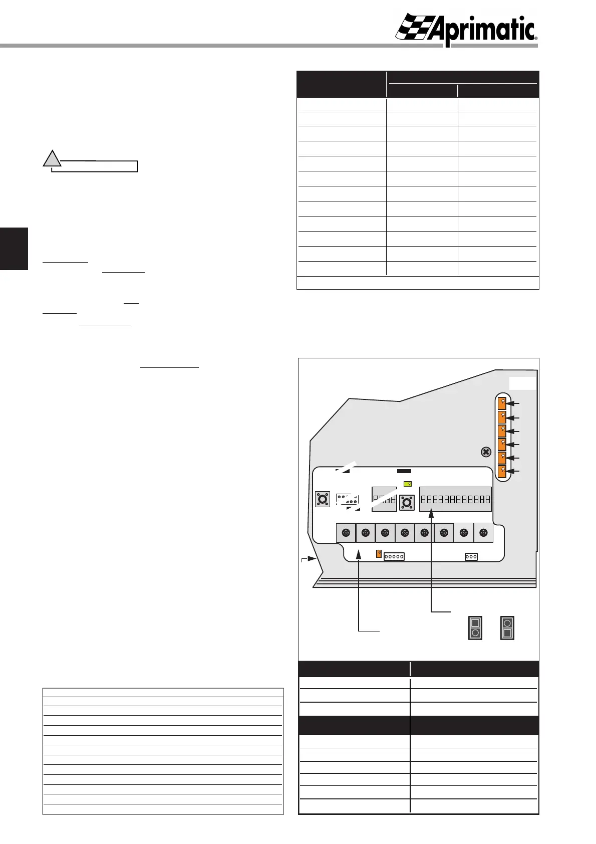
DL1
RESET
SW1
P1 P2 P3 P4 P5 P6 P7 P8
RIT. BN
ON
123456789101112
V. AVV. F. SPI. T. SOS. VELOC. % AP. P.
RADAR
SW2
DL2
J3 J10
DP2 DP1
ON
1234
Trimmer
DIPSWITCH
JP1
BUZZER
JP2
do not touch
do not touch
do not touch
do not touch
SPI
M/S
STOP
FOTO
RAD.2
RAD.1
EMR
LED
DL9
LED Function
DL1
DL2 (green)
DL9
(visible on J9 connector side)
diagnostics and alarms
mains power supply presence
lock inserted
EMR
RAD.1
RAD.2
FOTO
STOP
M/S
EMERGENCY pushbutton
ENTRANCE Radar
EXIT Radar
photocell
STOP pushbutton
Master/Slave mode
accessory devices connected to terminal board K3 as per
diagram in Fig. 7:
ONOFF
Starting up
fi g.8
Table 8
FACTORY SETTINGS (DIPSWITCH UNIT DP1)
1 OFF (fixed partial opening)
2
OFF (door free after break-in attempt)
3
ON (M/S disabled (1st input enabled))
4
ON (closing speed = 100% of opening speed)
5
ON (photocell contact = NC)
6
OFF (continuation during power failure)
7
ON (last operation = door opening)
8
OFF (electric lock disabled in exit only mode)
9
ON (emergency operation = door opening)
10
OFF (NO door release during power failure)
11
ON (disables STOP in Night lock mode)
12
OFF (not active)
Table 7
Table 6
 Loading...