K14117-8 11/07 Rev. A
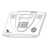
APX32EN
Security System
Quick Start Guide
U
UU
U
L
LL
L
APX32EN is not intended for UL985 Household Fire applications unless a 24-hour backup battery (P/N
LYNXRCHKIT-HC or LYNXRCHKIT-SHA) is installed.
Introduction
This Quick Start Guide can help you install the rechargeable APX32EN quickly and easily by providing the basic
steps for installation using the built-in defaults. For more detailed information and important notes, refer to the
APX32EN Installation and Setup Guide.
Installing APX32EN
Installation and Electrical Connections
Step Action
1. Install the control as follows:
a. Separate the front assembly from the back plate and disconnect the cable from the front assembly board.
Note: Disconnect the cable only from the front assembly board, not from the terminal block PC board.
b. Mount the back plate.
2. Make wiring connections as follows:
a. Connect the incoming phone line to either the 8-position jack or terminals 2 (TIP) and 3 (RING).
b. Connect the handset phone lines to either the RJ11 jack or terminals 4 (TIP) and 5 (RING).
Note: For full line seize operation, see the installation instructions.
c. If used, connect a piezo sounder to terminals 10 (+) and 11 (–).
d. If used, connect a bell to terminals 11 (–) and 12 (+).
e. If used, connect the IP or GSM communications device to the Alarmnet LRR/IP communications port.
f. Connect wires from the K10145X10 AC Transformer to terminals 15 and 16.
3. Make battery connections as follows:
a. Remove battery retainer.
b. Remove backing from tape on back plate.
c. Insert battery pack into back plate.
d. Install battery retainer.
e. Connect battery connector to receptacle on terminal block PC board.
f. Carefully reconnect the ribbon cable to the front assembly PC board connector (properly aligning the red
wire).
g. After all wiring connections have been made, snap the front assembly to the back plate so it is held by the
locking tabs.
h. Plug the transformer into a 24-hour, 110VAC unswitched outlet.
Note: Rechargeable batteries may take up to 48-hours to fully charge. “LOW BAT” message should clear within
four hours, or by entering Test Mode.