AQUABASEYFR-GB -ES 01-2007 VERSION 01/07 FR/GB/ES Page 10/10
3. DESCRIPTION
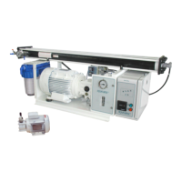
31. WATER SYSTEM (See Fig. 2p28, Fig. 18 & 19p26)
REP.
DESCRIPTION FUNCTION
EdM Hull fitting Always immersed, it insures continuous sea water feeding of the unit. Not included in the supplies.
V0 Hull valve Situated near the hull fitting, insures shutting of sea water feeding. Not included in the supplies.
A/B/
C/D
Feeding pipes Insures feeding of the unit through the filters.
1 Strainer Contains a washable element, which protects the Booster Pump against the coarsest impurities.
2 Cleaning valve Manual three-way valve allowing to feed the unit from a bucket which contains fresh water or chemical solutions, in order to
rinse or to clean the membranes.
3 Low Pressure Pump Feeds the filters under positive pressure and sufficient flow. Should be installed below the water line in order to avoid any
intake of air in the circuit.
4 Filter Contains elements insuring sea water filtering at 20µ and 5µ.
5 LP Switch Automatically stops the unit in case of insufficient feed water pressure.
6 LP Gauge Indicates the sea water feed pressure.
7 High Pressure Pump Driven by coupled electric motor, it raises sea water pressure to the required value.
8 Dampner Protects the membranes against high pressure variations.
9 HP Switch Automatically stops the unit in case of overpressure in the system.
10 R/O module Made up of pressure-resistant vessels, containing the membranes in which the desalination of sea water is carried out.
11 HP Gauge Indicates the pressure in the R/O membranes.
12 Pressure regulating valve Insures adjustment of the pressure in the membranes, conforming to instructions given in Chap.2.
13 Cleaning valve By opening this valve, the valve (2) itself being turning to rinsing position, the unit can be operated in closed circuit on a
bucket containing cleaning solutions. See Chap. 87.
14 Flow meter Indicates the flow of water produced by the water maker.
15 Salinity cell Continuously measures the salinity of the produced water and controls the valve (16) according to this measure.
16 Diversion valve Electromagnetic 3-way valve controlled by the salinometer. It automatically directs the produced water towards the tank if the
salinity is correct, or towards discharge to the sea, if it isn’t
L Reject piping Collects the concentrated brine produced by the membranes for discharge to the sea..
R Hull fitting Situated above the water line, insures brine discharge to the sea . Not included in the supplies.
E Rinsing pipes Insure feeding of the unit with the water or chemical solutions contained in an auxiliary bucket, during the membranes rinsing
and cleaning operations.
N Cleaning pipes Direct the unit discharge towards the auxiliary bucket, thus insuring membranes cleaning in closed circuit.
32. ELECTRIC BOX (See Fig. 3p28)
REP DESCRIPTION FUNCTION
30 Green selector switch Starting up of the unit and indication with an integrated signal lamp.
31 Red selector switch Stopping of the unit.
32 Salinometric indicator Shows the quality level of the produced water with four LED ( green, green, orange, red).
33 Production signal lamp Green LED indicating that the reject valve is in « production » position.
34 Salinometer Measures the salinity of the produced water with a cell ; shows the measure with the LED indicator (32) and controls the
diversion valve (16).
35 Control circuit Insures the connection between the different electrical control components.
36 Fuse Protection of the electric box.
37 Hour meter Indicates the running time of the unit.
40 Electric box
41 Transformer Supply of 24VAC current to the control box.
42 Contactor Feeds the booster pump electric motor.
43 Contactor Feeds the HP pump electric motor.
44 Circuit breaker Protection of the booster pump electric motor, in case of overload.
45 Circuit breaker Protection of the HP pump electric motor, in case of overload.
4. INSTALLATION
41. PREPARATION
The hull fitting and the hull valve are supplied and installed by the work site.
The sea water feeding hull fitting (EdM) should be placed as low as possible below the water line, in an area always immersed whatever the boat’s navigation rate may be.
The hull valve (V0) should be placed on the sea water feeding pipes, as close as possible to the hull fitting.
The reject hull fitting (R) should be placed above the water line.
42. PLACING THE UNIT
- The booster pump should be installed below the water line, as near of the hull valve as possible.
- The filters should be fixed vertically in place, by means of the equipped support.. If necessary, it can be slightly inclined in relatio
the vertical position.
- The HP pump set should be mounted horizontally on a rigid base, by means of its rubber mountings.
- It is allowed to install the R/O module in any position, vertically or horizontally, provided the pressure gauge and the press
remain a correct accessibility.
HP pump and R/O module are connected together by means of a 1500mm length flexible hose. Sometimes it is necessary to install
them in such a way, that the hose is too short. I this case, HP flexible hose of special
length is available as extra.
form
- The main module should
be bolted on a rigid
horizontal surface.
 Loading...