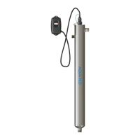
The AQUA FLO UV Disinfection System is an ultraviolet (UV) disinfection system designed to provide safe, microbiologically pure water for residential and multi-use applications. This system uses a chemical-free process to inactivate microorganisms present in the water supply, ensuring access to safe drinking water throughout the entire home.
Function Description
The core function of the AQUA FLO system is water disinfection using UV light. Water flows through a reactor chamber where it is exposed to UV-C light emitted by a UV lamp. This UV light inactivates bacteria, viruses, and other microorganisms by disrupting their DNA, preventing them from reproducing and causing illness. The system is designed to operate continuously to ensure optimal disinfection.
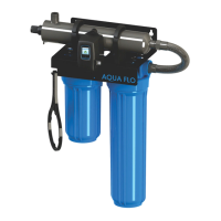
The effectiveness of the UV disinfection is dependent on water quality parameters such as hardness, iron, manganese, turbidity, and UV transmittance (UVT). Pre-treatment equipment, such as a 5-micron filter, is recommended to ensure these parameters meet the required levels for efficient UV penetration and complete disinfection.
Usage Features
The AQUA FLO system comes with various controllers and optional modules that enhance its usability and monitoring capabilities:
- Controllers:
- GEN4 Controllers (LB4 and LBH4 Series): These are simplistic in operation, featuring a tri-color LED that indicates system status and a 4-digit display for remaining lamp life. The LED is green when the UV lamp is on and within its operating age, and red with an audible buzzer when the lamp is off or expired. A button allows switching the display to show total running time.
- GEN5 & GEN6 Controllers: These controllers feature a full-color LCD screen that provides detailed system performance, fault messages, and system diagnostics. They include an "infinite expandability port" for optional modules. The GEN6 series specifically includes a UV intensity monitor.
- Power-up Sequence (GEN5 & GEN6): Upon startup, the controller runs a diagnostic sequence displayed on the LCD, including "system diagnostics" and "starting lamp." It then checks for and initializes any attached optional modules.
- Operational Screens (GEN5): The default screen is the "AQUA FLO Home Screen." Users can scroll through screens displaying "Lamp life remaining," "QR Code," "Contact Info," and "Maintenance Parts" by pressing a button on the controller.
- Operational Screens (GEN6): Similar to GEN5, but the "UV Intensity" screen replaces the home screen. This screen shows the level of UV light detected by the sensor, which can be affected by water quality, scaling, lamp failure, or expiration. If UV intensity drops below 56%, a warning sign appears, numbers turn red, and an audible chirp sounds every 15 seconds. Below 51%, the screen becomes solid red with a constant audible alarm, indicating "water may be unsafe for consumption." If a solenoid module is connected, it deactivates, shutting off water flow.
- Lamp Countdown Sequence: The system counts down the days until a lamp change is required. At 30 days remaining, a yellow caution indicator appears. At seven days, an additional audible chirp sounds. Past zero days, the LED or display turns solid red with a continuous buzzer. The audible alarm can be deferred for seven days by holding the controller button for five seconds, with up to three deferrals allowed.
- System Service Suggested Screen (GEN5 & GEN6): Every six months, this screen reminds users to maintain their UV system and pre-filtration. It's a prompt and does not trigger an alarm.
- QR Codes: The controllers display QR codes that link to the AQUA FLO website, providing information on replacement components and helpful video directories for system servicing (e.g., changing a UV lamp or quartz sleeve).
- Temperature Management Devices:
- Cooling Fan (for AQUA FLO-HO systems): Runs continuously to cool water by forced convection, powered independently.
- Temperature Relief Valve (TRV): Drains a small amount of water to allow fresh, cooler water to enter the system when temperatures rise, operating without power.
- Expansion Modules (for GEN5 & GEN6 controllers): These modules connect via an "Infinite Expandability Port" in a "daisy chain" configuration.
- UV Sensor: Monitors UV intensity (standard on GEN6, optional for GEN5).
- Solenoid Connection Module: Connects a normally closed line voltage solenoid valve to the system. On monitored systems, it closes if UV level drops below 50% or on lamp failure. A manual override mode allows water flow during an alarm if untreated water is needed.
- 4-20 mA Module: Outputs a 4-20mA signal of UV output to a remote device like a data logger or computer.
- WiFi Module: Connects the UV system to a smartphone, tablet, or computer via an app, allowing users to view system status, receive SMS/email alarms, and monitor UV health remotely.
- Remote Alarm Connection Module: Provides contacts for connection to a remote device such as a buzzer, light, or alarm system, indicating normal operation or fault conditions (Low UV, Lamp fail, Power Fail).
- Flow Meter: (Coming Soon)
Maintenance Features
Regular maintenance is crucial for the AQUA FLO UV system's effectiveness and longevity:
- Lamp Replacement:
- GEN4 Systems: After lamp expiration, the lamp must be replaced with the specified part number. The controller timer is reset by holding down the button for 10 seconds until "rSt3," "rSt2," "rSt1" is displayed, followed by a beep.
- GEN5 & GEN6 Systems: The replacement lamp comes with a new lamp key. The old key is removed and discarded, and the new key is inserted into the controller.
- General Procedure: Always hold UV lamps by their ceramic ends, not the quartz. Cotton gloves are recommended to prevent oils from hands from blocking UV light.
- Quartz Sleeve Cleaning: The quartz sleeve may require periodic cleaning, at least annually, depending on water quality. The procedure involves shutting off water flow, disconnecting power, releasing water pressure, removing the ground screw, disconnecting the lamp connector and lamp, unscrewing the gland nut, and then gently twisting and pulling out the quartz sleeve and o-ring. The sleeve is wiped down with a commercial scale cleaner (e.g., CLR® or LIME-A-WAY®) using a soft, lint-free cloth to remove scaling or iron deposits, ensuring no moisture enters the sleeve. After drying, the o-ring and sleeve are reinstalled.
- UV Sensor Cleaning (GEN6 systems only): The UV sensor may also require annual cleaning. This involves shutting off water flow, disconnecting power, releasing water pressure, unscrewing the sensor nut, and slowly pulling out the sensor. The flat portion (sensor face) is wiped with isopropyl alcohol using a clean, lint-free cloth. The sensor is then reinstalled.
- System Disinfection: After a new installation, or any time the UV system is shut down or inoperative, the entire home's plumbing lines should be disinfected. This involves removing "dead ends," plugging in the UV system, filling the last filter sump with household bleach, running water at all outlets until bleach is smelled, waiting 30 minutes, reinstalling the filter, and flushing until chlorine is no longer detected.
- Leak Checks: After plumbing connections are completed, slowly turn on the water supply and check for leaks. The most common leak source is an improperly sealed o-ring on the reactor. For older systems, draining the reactor, removing, drying, and reapplying silicon grease to the o-ring is recommended.
- Controller Mounting: The controller should be mounted vertically above or beside the reactor to prevent moisture from affecting connections. For monitored systems, the sensor connector is inserted into the IEP port, and the controller power cord is plugged in last for the sensor to be recognized.