— 3 —
Customer Service (800) 945-2726 • www.aquaticbath.com
Installation Instructions
4-Piece A
2
Composite Shower System Models
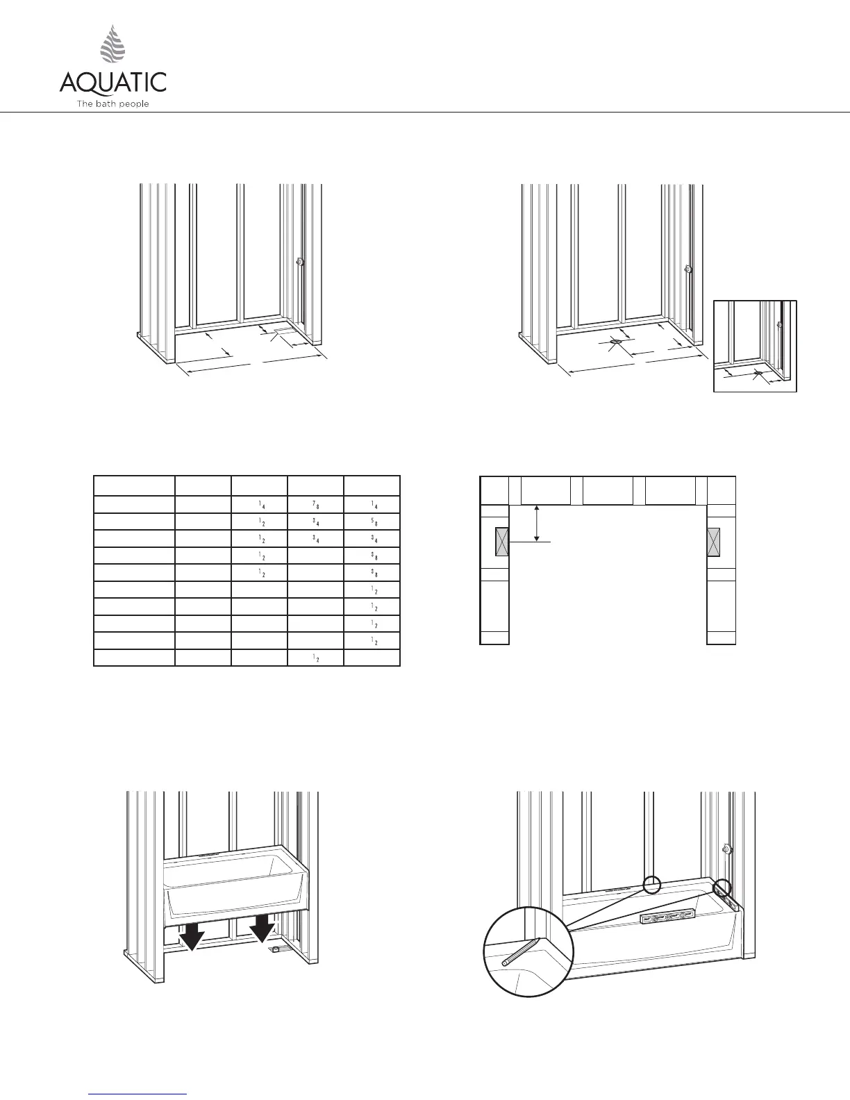
Check dimensions. For tub-showers, refer to Diagram 1A; for showers, refer to Diagram 1B.
NOTE: If you’re adding additional accessories such as a grab bar–additional framing may be needed for support.
6"x12"
AA
AA
C
C
DD
B
B
Additional stud may be required for vertical backwall flange.
Stud @ 7
7
⁄8” CL from back, on both sides. Stud can be turned
for easier installation.
6"Dia.
AA
C
C
DD
B
B
6"Dia.
DD
CC
1A 1B
32
Pre-install unit to ensure framing pocket is plumb, square and a level
installation can be achieved (see steps 3 through 9).
Adjust framing as needed – Shim where necessary.
*Review Tech Data at a2bath.com for more detail.
Note: 6030CTS is shown for illustrational purposes.
Level and mark all sides. Front apron should be firmly on the floor.
5
Lift and place the base into framing.
4
7
7
⁄8"
C
L
Models A B C D
6030CT/CTM 60” 31
1
⁄4
” 2
7
⁄8
” 14
1
⁄4
”
6030CTMIN/CTMM 60” 31
1
⁄2
” 2
3
⁄4
” 14
5
⁄8
”
6032CTMIN/CTMM 60” 33
1
⁄2
” 2
3
⁄4
” 15
3
⁄4
”
6036CT/CTM 60” 37
1
⁄2
” 2 17
3
⁄8
”
6042CT/CTM 60” 43
1
⁄2
” 2 20
3
⁄8
”
3232CPAN 32” 32” 16” 15
1
⁄2
”
3636CPAN 36” 36” 18” 17
1
⁄2
”
4834CPAN 48” 34” 24” 16
1
⁄2
”
6034CPAN 60” 34” 30” 16
1
⁄2
”
6030CPAN 60” 30” 8
1
⁄2
” 14”
INSTALLATION PROCEDURE