11
5 MAINTENANCE
In case of failure, check the fuse and the wiring (Fig. 2).
5.1 Troubleshooting
FAULT CAUSE REMEDY
The LEDs turn on but
are unable to control the
relevant valves
Disconnected connectors • Connect the connectors.
All LEDs are OFF and
the valves do not work
Internal protection is active
• Cut-off the supply and wait for at least 20 seconds
before switching the control box on.
If the problem persists, please contact the nearest
Assistance Centre.
Burnt fuse inside electric
circuit (Fig. 2)
• Replace the fuse. If the problem persists, please
contact the nearest Assistance Centre.
Power supply failure • Check power supply.
Switches are set to OFF
(lever down) but valves
are open
Reversed power cable • Check power cable connection.
6 TECHNICAL DATA
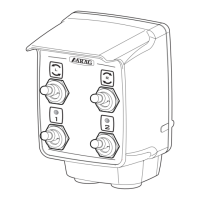
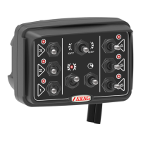
Description 4669 series control box
Power supply 12 Vdc (Vmin 9 / Vmax 16)
Max. switching current per each output (section) 3 A
Max. switching current per each output (Adjustable
actuators / Guard actuators)
5 A
Working temperature -20 °C ÷ 55 °C / -4 °F ÷ +131 °F
Stocking temperature -20 °C ÷ 55 °C / -4 °F ÷ +131 °F
Output protection through resettable fuse present
Dimensions 80 x 115 x 93 mm (harness excluded)
Weight 600 ÷ 1396 g (according to the type)
7 DISPOSAL AT THE END OF SERVICE
Dispose of the system in compliance with the established legislation in the country of use.
Tab. 2
 Loading...