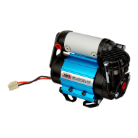
4.3 Connecting The Power Wires
IMPORTANT :
Although the wiring loom in this kit was designed to work with either a
12 volt or 24 volt system, the DC motor of the compressor has been designed
ONLY for use on one specific voltage system.
Make sure you have the CKMTA12 compressor kit for 12V systems or the
CKMTA24 for 24V systems.
Connecting a compressor to an incorrect voltage level will cause extensive
damage to the compressor’s DC motor, so carefully follow the power connection
instructions below that apply to the vehicle.
IMPORTANT :
Never connect the power to the compressor while the vehicle key
is in the ACC position, as this may result in accidental compressor start-up.
Plug the sealed connector on the supply loom #180414 to the compressor.
Carefully route the supply loom from the compressor mount position to the battery
position.
4.3.1 Power Connection To A 12V Vehicle / System
Trim all 4 wires to the correct length for connection to the battery.
NOTE : If any of the wires require extra length to reach the battery then splice in an
extension using ONLY wire that is of the same gage or bigger than the wire
being lengthened.
NOTE : The inline fuse should be located as close to the battery connection as
possible. Never eliminate any fuses when shortening the RED wire, and
only ever lengthen the RED wire on the opposite side of the fuses from the
battery.
Crimp suitable gage automotive eye terminals (not supplied) onto each of the heavy gage
(5mm
2
[10AWG]) RED wires.
Crimp a suitable gage automotive eye terminal (not supplied) onto the heavy gage (8mm
2
[8AWG]) black wire that is marked with a white stripe (BLK-WHT).
NOTE : In a 12V system the 2 black wires (BLK and BLK-WHT) will be joined
together, so they may be crimped together into the same eye terminal if
desired. Refer to wiring diagram in Fig 9.
Crimp a suitable gage automotive eye terminal (not supplied) onto the lighter gage solid
black wire with no stripe (BLK).
Connect the RED wire to the positive (+) terminal of the battery by securing the eye
terminal under the nut of the battery terminal clamping bolt.
Connect both of the black wires (BLK and BLK-WHT) to the negative (-) terminal of the
battery in the same way.
Secure all loom wiring with cable ties along its entire path, as vibration could cause wear
to the insulation over time which could result in a dangerous electrical short.