12
5. KU 8-exhaust system
5.1 Assembling and mounting of KU 8-exhaust system
The following description on assembling and mounting of KU 8-exhaust system is
valid for whether it is a KU 8 or if it is a VFCB-121. The mounting order is the
same for both models.
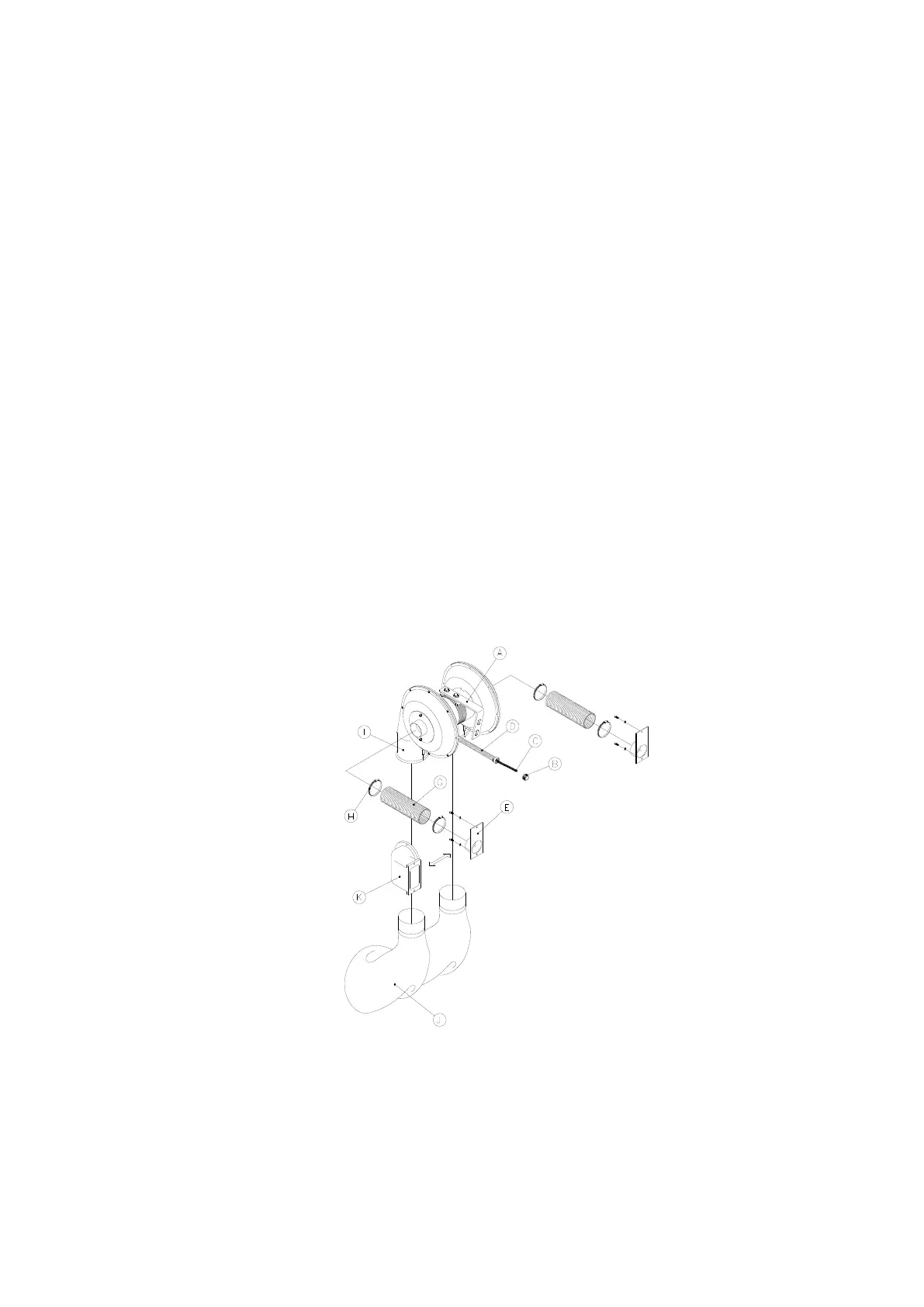
The clamp (A) (see fig.: 4.1) is first mounted at the back of the E 308 and then as
shown on the KU 8-motor. Dismount the blind stop at the back of the E 308 and
mount the connector (B). Dismount the switch on the E 308 without unscrewing
the wires. Lead the wire (C) through the connector (B) and screw the protection
hose (D) onto the connector (B). Mount the wires from the KU 8-exhaust system
on the switch (see wiring diagram). Mount switch again. Dismount the blind stops
on the cover or the belt arm and instead mount the lid (E) with the exhaust
connecting pipe. To the last fit the suction hoses (G) and mount them with the
straps (H).
Before use the KU 8-exhaust system must be mounted with suction hoses on the
exhaust connecting pipe (I), which then is connected to the central exhaust
system. If the central exhaust system is not connected to a cyclone the exhaust
from the KU 8-exhaust system must be connected to a cyclone and then
connected to the central exhaust system. If there is no central exhaust system
dust bags (J) must be mounted on the exhaust connecting pipe (I).
In case the KU 8-exhaust system is mounted on a E 308 double grinder the cast
bends (K) can be used to mount the KU 8-exhaust system to the grinding machine
so that the clamp (A) and the suction hoses (G) with accessories can be left out.
Fig.: 5.1
5.2 Maintenance of the KU 8-exhaust system
Nothing on the KU 8-exhaust system needs maintenance except for it is
necessary regularly to check that the suction hoses are in goods condition and
that the channels are free of grinding dust.


 To Next Page