The CPU
is located at component position
U701
and
can be found on the front panel display board, the
CPU contains a Keyboard scan this is driven from
the resistive array powered by the
VREF
output at
Pin 98 the voltage drop sensed can be seen on Pin
97 (AVSS) and as 4.9 V on R701.
The CPU also receives and decodes the IR from
both the display board remote receiver and the rear
panel remote input 3.5mm jack.
Please note: The IR from the from the display panel
pickup device is not driven directly into the CPU it
takes a path onto the main board and into the IR
micro circuit the signal is mixed into the rear panel
sourced IR signal by the circuit based around
Q301,
Q302, Q303 the result is a signal called RMIN this
signal is fed back to the display board and into Pin 32
of the CPU.
IR RC5 electrical signals driven into the rear panel
3.5 mm jack passed thru the Opto-isolator package at
location OP301 the signal is then clamped to 3v9 by
Zener diode D301 before reaching R-C filter network
provided by C340, C341 and R304 final drive is
supplied by U301(a) and U301(b).
Digital to Analogue conversion
The BCK, PCMD and LRCK lines from the DSP are
buffered by
U406
(74HCU04) before arriving at the
D to A converter at location U401 (WM8740) these
lines are now labelled as BCLK, ADATA and
LRCKIN
(left, right clock in).
The WMA740 DAC is driven from its own 5 Volt
supply, this can be seen on pin 8 as
DVDD
.
The de-emphasis flag arrives from the DSP on pin
number 27 (high = on)
The master audio clock arrives at pin 5 labelled at
DACLK and is supplied by the previously mentioned
circuit built around
U402
(see page 2)
The Audio outputs from the DAC can be seen via
an x10 probe on
R416
and
R414
Left channel and
R415 and R417 Right channel, these are differential
outputs and as such will have +/- offset respectively.
The differential Audio outputs from the DAC are
summed by U403a and U404a before driving into the
output Op-amps
U403b
and
U404b
, D.C errors are
removed by servo Op-amps U405a and U405b
providing a D.C coupled output.
Optional DAC stage notes
As previously mention the main board has been
designed to provide a platform for other players
within the Diva range and as such provisions
have been made for the addition of optional D to
A stages; these can be connected to the flexi foil
sockets at locations SK203 and SK301 see Fig
3a/b for relevant pin information for these
sockets.
When fitting an optional Audio stage we need to
adjust the jumper settings on the existing main
board information on jumper settings appear
within Fig 4.
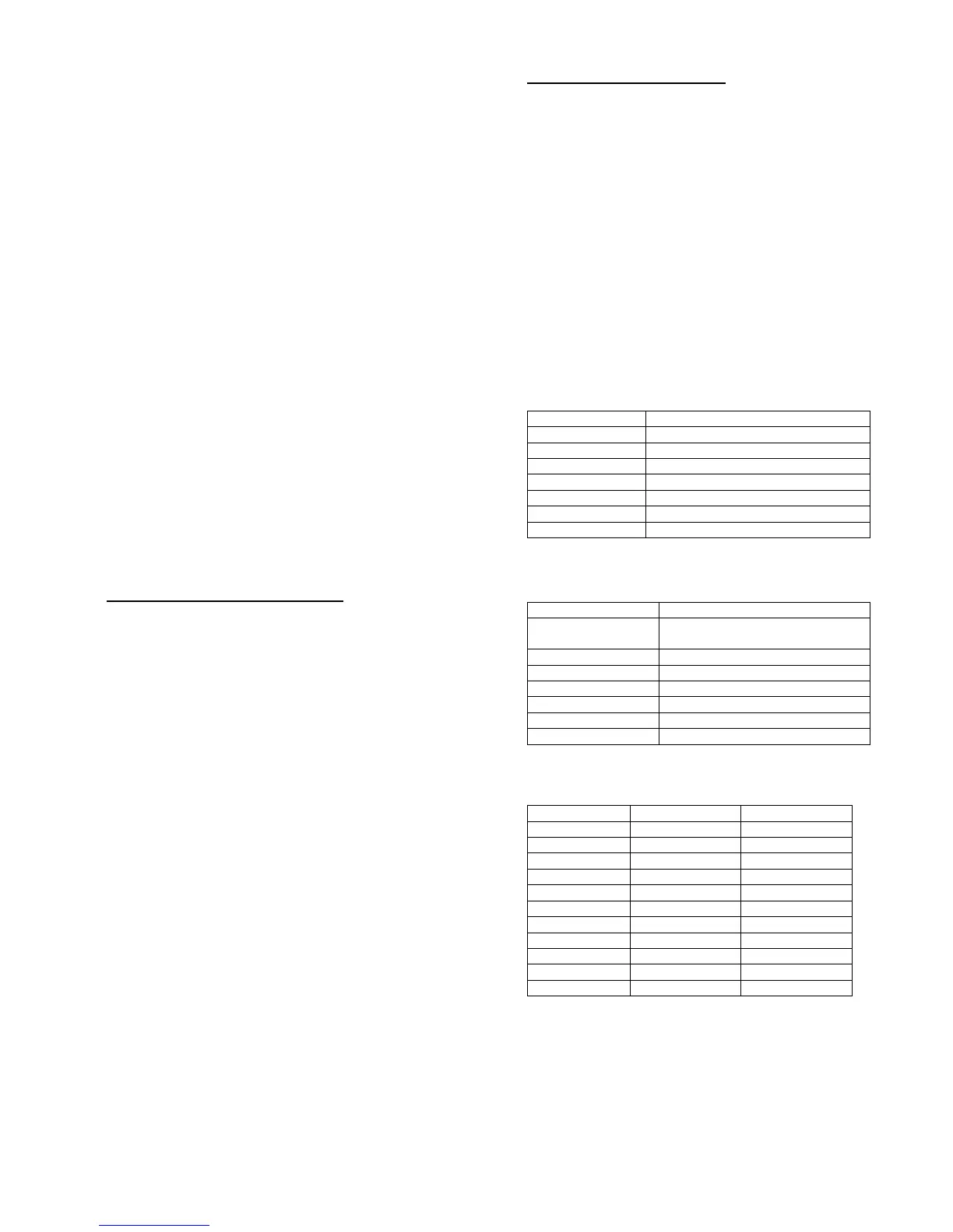
Fig 3a Pin connections for SK203.
Pin Number(s) Power supply and function
1 Digital ground
2,6,7,12,13,19,20 Analogue ground
3,4,5 +11v unregulated
9,10,11 +5v Digital supply (DAC)
14,15 +5v Analogue supply
16,17,18 -12v Analogue supply
21,22,23 +12v Analogue supply
Fig 3b Pin connections for SK301.
Pin Number(s) Function
1,2,5-9,18-
20,23,26,28,30,32.
Analogue ground
17 Emphasis
21 Reset
22 Mute
25 Left/Right clock in (LRCKIN)
27 A DATA
29 B-Clock (BCLK)
Fig 4. Option jumper settings.
Location CD73 Option
PL100 Open Open
PL202 Open Short
PL203 Short Open
PL204 Open Short
PL205 Short Open
PL300 1/2 Short 1/2 Open
PL300 2/3 Open 2/3 Short
PL400 Short Open
PL401 Short Open
PL402 Short Open
PL403 Open Short