Shade Adjustment (refer to Figures 1 through 4):
See Filter Specifications (Table 1) for filter specifications.
See CE Shade Selection Guide (Table 2) for recommended shades for arc welding applications.
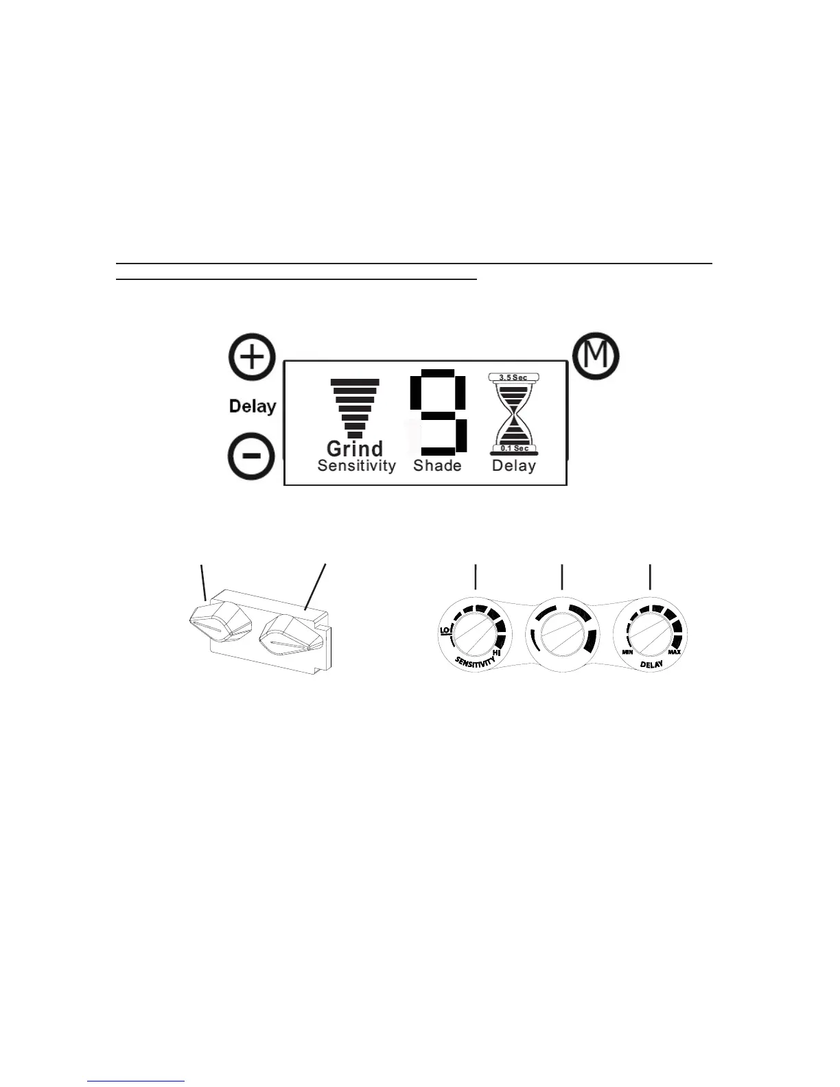
Digital LCD Controlled Variable Filters (see Figure 1): Briefly press the “Mode” button (see
Figure 1), the LCD mode will flash to indicate the current setting. Press and hold the “+” or “-”
button to change the setting. The number will change on LCD.
Analog Controlled Variable Filters (see Figure 2):
External Control: Set filter to desired dark shade with the shade knob located on the outside of
the helmet. The Shade Number will change on the LCD (see Figures 3 and 4) as the user turns
the knob up or down. Some models have a single external knob for shade only.
Internal Control: Set filter to desired dark shade with the shade knob located on the filter.
The configuration of internal controls vary; however, each knob is labeled according to function,
also, buttons are labeled or marked according to function.
Sensitivity Adjustment
Digitally Controlled Filters: Briefly press the “Mode” button (see Figure 1), the LCD mode will
flash to indicate the current setting (see Figure 3). Press and hold the “+” or “-” button to change
the setting.
Analog Controlled Filters: Models with external or internal control turn the knob to change the
sensitivity (see Figure 2), increasing or decreasing it. Some Digital LCD models will display the
level of sensitivity (see Figure 1), where more bars equals increased sensitivity.
X-TIG Mode:
Filters 5000VX, 5130VX, 5500VX, 7000VX, and 7500VX, have an X-TIG mode ideal for TIG
welding applications. When set to X-TIG, the digital display will show “X-TIG” in the
sensitivity column (see Figure 3b).
5000VX and 7000VX: X-TIG is accessed via an external switch on the outside control. Turn until
the control knob clicks into place and the LCD displays “X-TIG.”
5130VX, 5500VX, and 7500VX: Use the “+” button to set the sensitivity to the highest setting.
I-TIG Mode:
The iDF48 (USA) has iTIG mode. See the following page for more details.
- 2-
Shade
Adjustment
Sensitivity
Adjustment
Figure 2: Analog Controls
Figure 1: Digital Controls
Mode
Increase
Decrease