8
Installation, Operation & Maintenance Manual
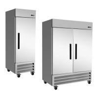
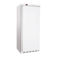
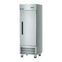
REACH-IN REFRIGERATORS AND FREEZERS
OPERATION
Refrigeration Cycles
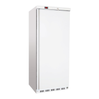
Refrigerators
The evaporator fans run continuously during the refrig-
eration cycles to maintain the factory set internal tem-
perature range at 34°F to 38°F. The door switch turns
on the lights when the door is opened.
1. Every 6 hours, the unit turns off and the controller
displays the defrost symbol this allows the evapora-
tor coil to clear the ice. When the coil temperature
reaches 41°F (or after 20 minutes) the unit re-starts.
2. The anti-condensation heaters (located on the door
frames) work in conjunction with the compressor.
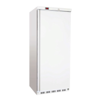
Freezers
The controller provides power to the condensing unit
and the evaporator fans during the refrigeration cycles
to maintain the factory set internal temperature range
at -3°F to -7°F. The evaporator fans run whenever the
evaporator coil temperature is below 54°F, except during
the defrost cycle when they cycle off. The door switch
turns on the lights when the door is opened.
1. Every 6 hours, the unit turns off and the controller
displays the defrost symbol this allows the evapora-
tor coil to clear the ice. When the coil temperature
reaches 45°F (or after 20 minutes) the unit re-starts.
2. The anti-condensation heaters (located on the door
frames) work in conjunction with the compressor.
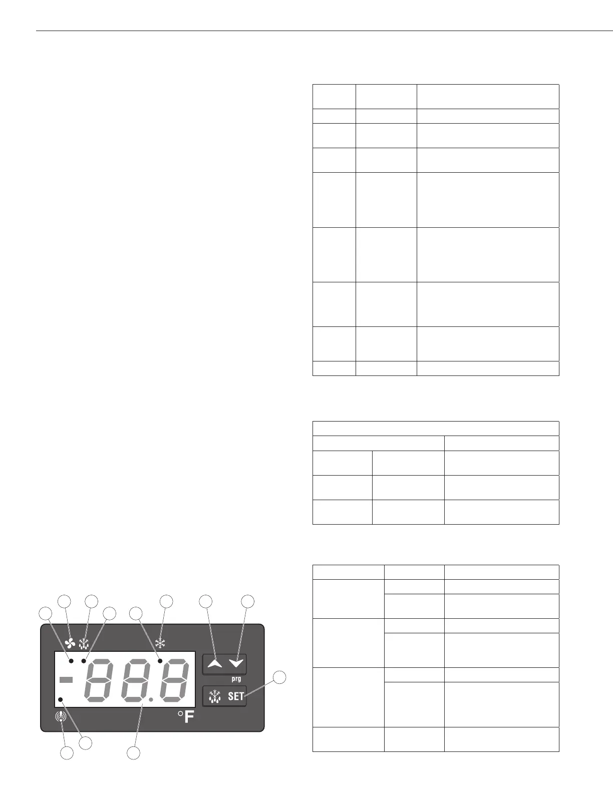
Front Panel Controls and Indicators
The front panel controls and indicators are used to set
and display the unit functions and status.
Callout
No.
Control /
Indicator
Function
1 Fan
Indicates the fans are running.
2 Defrost
Press to start the manual defrost
cycle.
3 Compressor
Indicates the compressor is
running.
4
Up Arrow
To display the last temperature
alarm.
In programming mode it
browses the parameter codes or
increases the displayed value.
5 Down Arrow
To display the last temperature
alarm.
In programming mode it
browses the parameter codes or
decreases the displayed value.
6 SET
Used to display a target set
point; in programming mode it
elects a parameter or conrm an
operation.
7 Display
Indicates the room temperature,
the set points and the alarm
codes.
8 Alarm
Indicates a temperature alarm.
Key combinations are used to perform functions that
cannot be performed with a single key.
Key Combinations
Press Keys Result
Up Arrow Down Arrow
Locks and unlocks the
keyboard.
SET
Down Arrow
Enters the programming
mode.
SET
Up Arrow
Returns to the room
temperature display.
The LED functions display operational conditions.
Callout No. Mode LED Function
1a
On
Fans enabled
Flashing
Fans delay after defrost
in progress
2a
On Defrost enabled
Flashing
-Programming phase
(ashing with “icon”)
- Drip time in progress
3a
On
Compressor enabled
Flashing
-Programming phase
(ashing with “icon”)
-Anti-short cycle delay
enabled
8a On
A temperature alarm
happened
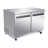
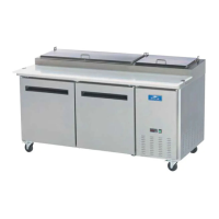
On/Off Switch
The on/off switch for the Pizza Prep tables is located
on the condenser compartment door. For the remaining
units, the on/off switch is located on the front of the bot-
tom shroud. When the unit is on, the green LED is on.