EasyManua.ls Logo

Arctic Cat 650 H1 Service Manual

Arctic Cat 650 H1
274 pages
To Next Page IconTo Next Page
Page #1 background imageLoading...
Page #1 background image
FOREWORD
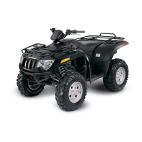
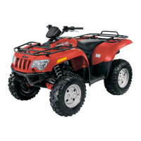
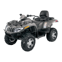
This Arctic Cat Service Manual contains service, maintenance, and troubleshooting information for certain 2010
Arctic Cat ATV models (see cover). The complete manual is designed to aid service personnel in service-oriented
applications.
Arctic Cat offers additional publications (when they become available) to aid in servicing other ATV models. To
service models not included in this manual, please refer to the following publications:
2010 Y-12+ Service Manual
2010 T-14 Service Manual
2010 300 DVX/Utility Service Manual
2010 366 Service Manual
2010 700 Diesel Service Manual
This manual is divided into sections. Each section covers a specific ATV component or system and, in addition to
the standard service procedures, includes disassembling, inspecting, and assembling instructions. When using this
manual as a guide, the technician should use discretion as to how much disassembly is needed to correct any given
condition.
The service technician should become familiar with the operation and construction of each component or system
by carefully studying the complete manual. This manual will assist the service technician in becoming more aware
of and efficient with servicing procedures. Such efficiency not only helps build consumer confidence but also saves
time and labor.
All Arctic Cat ATV publications and decals display the words Warning, Caution, Note, and At This Point to
emphasize important information. The symbol ! WARNING identifies personal safety-related information.
Be sure to follow the directive because it deals with the possibility of severe personal injury or even death. A
CAUTION identifies unsafe practices which may result in ATV-related damage. Follow the directive because it
deals with the possibility of damaging part or parts of the ATV. The symbol NOTE: identifies supplementary
information worthy of particular attention. The symbol
AT THIS POINT directs the technician to certain
and specific procedures to promote efficiency and to improve clarity.
At the time of publication, all information, photographs, and illustrations were technically correct. Some photo-
graphs used in this manual are used for clarity purposes only and are not designed to depict actual conditions.
Because Arctic Cat Inc. constantly refines and improves its products, no retroactive obligation is incurred.
All materials and specifications are subject to change without notice.
Keep this manual accessible in the shop area for reference.
Product Service and
Warranty Department
Arctic Cat Inc.
© 2009 Arctic Cat Inc. September 2009
®™ Trademarks of Arctic Cat Inc., Thief River Falls, MN 56701

Manual
Table of Contents

Other manuals for Arctic Cat 650 H1

Questions and Answers:

Arctic Cat 650 H1 Specifications

General IconGeneral
BrandArctic Cat
Model650 H1
CategoryOffroad Vehicle
LanguageEnglish

Summary

Section 1 General Information Specifications

General Specifications

Details general specifications for the ATV models.

Torque Specifications

Lists various torque specifications for different components.

Break-In Procedure

Outlines the recommended break-in procedure for new ATVs.

Gasoline Oil Lubricant

Provides recommendations for fuel, oil, and lubricants.

Section 2 Periodic Maintenance

Periodic Maintenance Chart

A table outlining maintenance intervals and tasks.

Air Filter

Details the procedure for removing and inspecting the air filter.

Valve Tappet Clearance

Explains how to check and adjust valve clearance using a feeler gauge.

Engine Transmission Oil Filter Strainer

Steps for changing engine oil, filter, and strainer.

Hydraulic Brake Systems

Procedures for checking and bleeding hydraulic brake systems.

Checking Replacing V-Belt

Instructions for removing and replacing the V-belt.

Section 3 Engine Transmission

Engine Transmission Specifications

Lists specifications for engine and transmission components.

Troubleshooting

Diagnoses and provides remedies for common engine and transmission problems.

Removing Engine Transmission

Step-by-step guide to removing the engine/transmission from the frame.

Top-Side Components

General advice on servicing top-side components efficiently.

Left-Side Components

Procedure for removing left-side components.

Right-Side Components

Procedure for removing right-side components.

Center Crankcase Components

Procedure for separating crankcase halves.

Section 4 Fuel Lubrication Cooling

Fuel Lubrication Cooling

Overview of the fuel, lubrication, and cooling systems.

Carburetor 400 650

Procedure for removing the carburetor.

Electronic Fuel Injection EFI

Troubleshooting common EFI system issues.

Gas Tank

Procedure for removing the gas tank.

Oil Filter Oil Pump

Steps for changing engine oil, filter, and strainer.

Liquid Cooling System H1 H2

Overview of the liquid cooling system for H1/H2 models.

THERMOSTAT

Procedure for installing the thermostat on H1 models.

WATER PUMP H1

Procedure for removing the water pump.

Electric Fuel Pump Fuel Level Sensor EFI

Procedure for testing the electric fuel pump and sensor.

Vacuum Pulse Fuel Pump 400 650

Procedure for testing the vacuum pulse fuel pump.

Troubleshooting 400 650

Diagnoses and provides remedies for carburetor-related problems.

Section 5 Electrical System

Electrical System

Overview of the ATV's electrical system.

Specifications

Lists specifications for various electrical components.

Battery

Information on battery specifications and maintenance.

Power Distribution Module PDM

Location and inspection of fuses in the PDM.

ECU Error Codes EFI

Steps to read and interpret ECU error codes.

Throttle Position Sensor TPS EFI

Procedure for installing and adjusting the TPS.

Troubleshooting

Diagnoses and provides remedies for electrical system issues.

Section 6 Drive System

Drive System

Overview of the ATV's drive system components.

Front Differential

Procedure for removing the front differential.

Drive Axles

Procedure for removing and assembling drive axles.

Rear Gear Case

Procedure for removing the rear gear case.

Hub

Procedure for installing the wheel hub.

Hydraulic Brake Caliper

Procedure for removing and disassembling the brake caliper.

Troubleshooting Drive System

Diagnoses and remedies for drive system issues.

Section 7 Suspension

Suspension

Overview of suspension system components.

Shock Absorbers

Procedure for removing and installing shock absorbers.

Front A-Arms

Procedure for removing and installing front A-arms.

Rear A-Arms

Procedure for removing and installing rear A-arms.

Wheels and Tires

Information on tire size, inflation, removal, and installation.

Troubleshooting

Diagnoses and remedies for suspension and steering issues.

Section 8 Steering Frame

Steering Frame

Overview of steering and frame components.

Steering Post Tie Rods

Procedure for removing steering post and tie rods.

Handlebar Grip

Procedure for removing handlebar grips.

Steering Knuckles

Procedure for removing and disassembling steering knuckles.

Measuring Adjusting Toe-In

Steps for measuring and adjusting front wheel toe-in.

Front Rack

Procedure for removing and installing the front rack.

Front Body Panel Side Panels

Procedure for removing front body and side panels.

Footrests

Procedure for removing and installing footrests.

Exhaust System

Procedure for removing and installing the muffler.

Taillight Assembly

Procedure for removing the taillight assembly.

Seat

Procedures for removing and installing the seat.

Cargo Box TBX

Procedure for removing and installing the cargo box.

Troubleshooting

Diagnoses and remedies for steering and frame issues.

Section 9 Controls Indicators

Hand Brake Lever Master Cylinder Assembly

Procedure for removing the hand brake lever assembly.

Throttle Control

Procedure for removing the throttle control.

Shift Lever

Procedure for removing the shift lever.

Speedometer Tachometer LCD

Procedure for replacing the speedometer.

Related product manuals