5
Műszaki tudnivalók
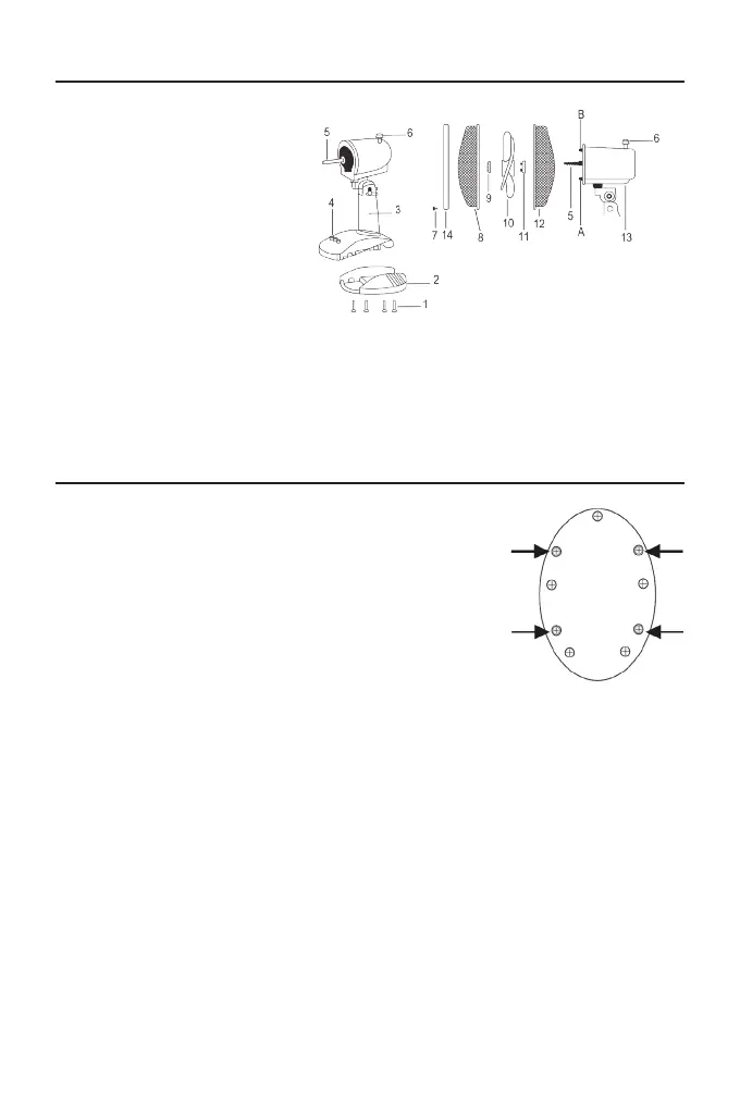
Összeszerelés
1. Az alapot rögzítsük a fő egységhez a tartozékként járó 4
db csavarral (lásd a jobb oldali ábrán).
2. A motor tengelyről (5) csavarjuk le a hátsó rácsot rögzítő
anyát (11): ehhez az anyát forgassuk az óramutató járá-
sával ellentétes irányba.
3. A hátsó rácsot (12) illesszük a motor tengelyre (5)
ügyelve, hogy a hátsó fogantyú felfelé nézzen, és a
rögzítőcsapok (A-B) beleüljenek a hátsó rács függőle-
ges lyukaiba. Csavarjuk be a rögzítő anyát (11): forgas-
suk az óramutató járásával egyező irányba.
4. A ventilátort (10) illesszük a motor tengelyre (5), majd a
ventilátor rögzítő anyát (9) az óramutató járásával egyező irányba forgatva rög-
zítsük a ventilátort.
5. Hajtsuk ki az elülső rács (8) rögzítőkapocsait, majd illesszük egybe a hátsó rács-
csal (12) ügyelve, hogy a központi csapon található logó vízszintesen, a padló-
val párhuzamosan fusson.
6. A megfelelő helyzetet megtalálva pattintsuk helyére a rögzítőkapcsokat, majd
helyezzük a rácsra a biztonsági gyűrűt (7).
1. Csavarok (4 db)
2. Alap
3. Fő egység
4. Kezelőpanel
5. Motor tengely
6. Forgó mozgás gomb
7. Biztonsági gyűrű
8. Elülső rács
9. Ventilátor rögzítő anya
10. Ventilátor
11. Hátsó rács rögzítő anya
12. Hátsó rács
13. Motor
14. Rögzítőanya
11
Assembling
Technical informations
1. Screws (4 pieces)
2. Base
3. Main body
4. Control panel
5. Motor shaft
6. Oscillation knob
7. Safety screw
8. Front grille
9. Lock ring of the fan
10. Fan
11. Lock ring of the back
grille
12. Back grille
13. Motor
14. Lock ring
1. Mount the base on the main body xing it with the 4 screws provided
as shown in gure.
2. Unscrew the nut of the grid xing rear (11) from
the drive shaft (5) by turning counterclockwise.
3. Insert the rear grille (12) on the motor shaft
(5) making sure that the handle on the back is
facing upwards and the locking pins (A-B) are
in the vertical holes of the rear grille. Screw the
locking ring (11) by turning it clockwise.
5. Insert the fan (10) on the motor shaft (5)
and fasten the proper lock ring (9) by rotating
counterclockwise.
6. Open the clips of the front grille (8) and place
it on the back grille (12) making sure that the
logo on the central stud is placed horizontally, parallel with the oor.
7. Find the proper position to lock the clips and insert the safety screw
of the grille (7).
6
1. Montare la base sul corpo principale ssandola
con le 4 viti in dotazione come mostrato nella
gura a lato.
2. Svitare la ghiera di ssaggio della griglia
posteriore (11) dall’albero motore (5) ruotandola
in senso antiorario.
3. Inserire la griglia posteriore (12) sull’albero
motore (5) in modo che la maniglia posta sul
retro di essa sia rivolta verso l’alto e che i due pin
di incastro (A-B) si inseriscano sui fori verticali
della griglia posteriore. Avvitare la ghiera di
ssaggio (11) ruotandola in senso orario.
4. Inserire la ventola (10) sull’albero motore (5) e ssarla ruotando in
senso antiorario l’apposita ghiera di ssaggio (9).
5.Allentare la vite di sicurezza (7) dell’anello di chiusura (14) e posizionarlo
sulla griglia posteriore.
6. Posizionare la griglia anteriore (8) su quella posteriore (12) in modo
che il logo sulla borchia centrale sia in posizione orizzontale parallela al
pavimento e in modo che l’anello la agganci.
7.Trovata la giusta posizione stringere la vite di sicurezza (7)
Informazioni tecniche
1. Viti (4 pcs.)
2. Base
3. Corpo principale
4. Pannello comandi
5. Albero motore
6. Manopola oscillazione
7. Vite di sicurezza
8. Griglia anteriore
9. Ghiera di ssaggio
ventola
10. Ventola
11. Ghiera di ssaggio
griglia posteriore
12. Griglia posteriore
13. Corpo motore
14. Anello di chiusura
A-B. Pin di incastro della griglia posteriore
Assemblaggio
 Loading...