Technlcal data
Voltage
Current consumption
High/Low
At
start
Supplied
Fuel
effect
Output
Fuel
Fuel
consumption
Fuel
operahng
pressure
Airflow
Weight
Size
Length
widrh
Height
Functlon
descrlptlon
Start
The
heater is
started
by
means
of the
switch,
which
gives
a startsignal
to the
control
unit
which will then
feed cur-
rent
to the
glowplug.
The fan
motor
will start
on low
speed.
After
a
time
delay
of about 50 seconds
the fuel
pump
is
connected
and
the
fanspeed
will
increase. Combustion
begins
with-
in about
10 seconds. The
flame sensor
sences
this and disconnects
the
glow
plug.
lf the heater
does
not
ignite at
first
start
a second
start automatically
will
be
done.
Operatlon
The
heater continues
to burn
until the
set
cabin
temperature is reached.
Full
or
half effect
is
manually
regulated
on
the
cabin thermostat.
Stop-
heater
The heater
is switched off
by means of
the control
switch.
After
switching
off
the
heater,
the fan motor continues
to
run for approximately
one
minute.
Safety
equlpment
At the start
period
the control
unit
controls
that
the flame sensor
and the
fuel
pump/
overheating
thermostat
are
intact.
A safety
timing circuit
will
cut
the fuel
supply
within 180 seconds
if two
failed
start attempts
are made.
A
low
voltage
protection
prevents
start
and operation
if the
voltage should
go
below
10.5 V.
If combustion
should stop
a flame sen-
sor senses
this and
automatically
switchs
off
the heater.
The
overheating
thermostat
willcut the
fuel supply
if there
is
a
risk for over-
heating.
A manual re-set after
cooling
must
be
done.
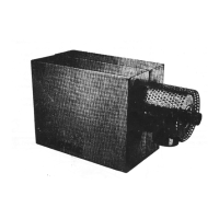
lnstallation
Locatlon
(fig.
i)
The
heater
is
placed
in a
suitable
place
outside
the area
which is to be heated.
Suitable
places
are in
the afterly
sto-
wage space
or the engine
space,
(alt-
hough
not ln the case
of
petrol
englnes).
Place
the
heater so that it
is
easily
accessible
to normal service and attach
it
with four screws through
the holes,
@
6
mm
in the
bottom
of the casing.
(according
to the enclosed drilltempla-
te).
The
place
where the heater is installed
must have enough
air for the
convec-
tion
(min.
2
sq.
dm). At increased
need
of heat
cabin air can be recycled.
Ensure that there
is
sufficient space to
manipulate
the cover clips and also to
remote the cover.
IMPORTANT
In
order
for the wananty to be
valid,
the installation must be
carried out according
to the
installation instructions.
Warm
alr
(fig.
2)
Fresh air
is normally
taken
from the
space suffounding
the heater. Ensure,
however
that there
is adequate ventila-
tion for
the
continued
replenishment
of
fresh air. This ensures that
the
heating
is
performed
by new, dry and
warm
air.
If
the heater is located in
the
engine
space or other
place
where
the
air
is
contamined,
fresh
air must
be supplied
from a more suitable
place,
via an air
hose.
The warm air is distributed throughout
the boat by means of a
flexible air
hose, inside diameter 65
mm. The
installation
is simplified
by using acces-
sories such
as hose-joints,
pipe
bends
air-outlets and
Y-piece, Minimum
hose
length 3
m, maximum hose
length 10
m.
Every bend reduces
the max.
length
accordlng
to
the below
mentloned.
90'bend
correspond to I
m
45'bend conespond
to 0,3
m
Hosetype: Westaflex APK
A
65.
The air
hose is
located
in
it's desired
position
with
clamps.
At
passage
through bulkheads etc,
a
@
72 mm
hole shall be cut.
In order to reduce the noice
level,
a
silencer
is installed
on
the heater
fresh
air side and combustion
air
intake.
Exhaust outlet and
combustlon
alr
lnlet
(figure
2l
The combustion air
is
taken up
through a separate combustion
air
hose. lt
is
extended
through
the
heater
box and connected
to a special
air inta-
ke. The
hose
is
placed
so
that a
highest
point
is reached between
the
heater and outlet, a so-called
"goose-
neck", see figure below.
The
insulated
exhaust hose
is
assembled
with
hose
72V
2,5Nr,7
A
114
3600
w
2700t1400w
Diesel
0,36/0,18
I
1000 mmVP
1ü) m3/h
7,5 Ks
380
mm
160 mm
230 mm
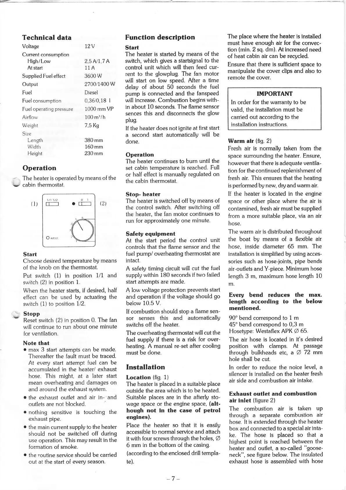
Operation
-
The
heater is operated
by means of
the
tv
cabin
thermostat.
Start
Choose
desired
temperature by
means
of
the knob on
the thermostat.
Put
switch
(1)
in
position
1/1 and
switch
(2)
in
position
1.
When the
heater starts,
if desired,
half
effect
can be
used by
actuating
the
switch
(1)
to
position
1/2.
Stopp
Reset switch
(2)
in
position
0.
The fan
will continue
to run
about one
minute
for
ventilation.
Note
that
.
max
3
start attempts
can be
made.
Thereafter the fault must
be traced.
At
every
start attempt
fuel can
be
accumulated in the
heater/ exhaust
hose. This might, at
a later start
mean overheating
and damages on
and around the exhaust
system.
o
the exhaust outlet and
air in- and
outlets are not blocked.
o
nothing sensitive
is touching
the
exhaust
pipe.
o
the
main current supply
to
the heater
should
not be
switched
off during
use
operation.
This may
result
in
the
formation
of smoke.
o
the
routine
service
should
be carried
out at the
start
of
every
season.
QI
il)
l/l
1/2 0
I
Tf---]
0 Tr-__l
O
rn,rr
-7
-
 Loading...