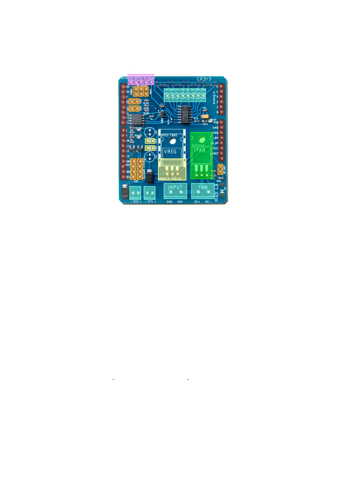
Figure 2: Layout of TC4+ through-hole components.
2 Assembly (kit version)
If you purchased a TC4+ KIT, it will come with all surface-mount devices sol-
dered, and loose through-hole components which you will have to solder yourself.
Figure 2 shows the location of these components in different colours:
• Dark Red: Stackable headers.
• Orange: Male headers; break apart as necessary. [1]
• Pink: Angled female header.[2]
• Blue/Turquoise: Screw terminals. [2]
• Yellow, labelled VREG: Voltage regulator. The kit comes with a R-78E5.0
switching regulator.
• Yellow, C12/C13: 10uf ceramic capacitors. C1/C2 are not used with the
R-78E5.0 switching regulator.
• Green, labelled TFAN: IRF540 transistor. Optionally fixed to board with
M3 screw.
Notes: [1] BT SEL (2x3, top left) and BT RST (1x2, bottom right) are for
jumpers, so male headers are required. For the I2C, IO2 and IO3 headers, a
different connector could be used if preferred.
[2] Included connectors are suggestions – any other 2.54mm / 5.08mm spaced
header could be used. For the Bluetooth board, an angled female 4/5 pin header
will have the Bluetooth module horizontal next to the TC4+ shield. For vertical
BT module, use a straight female 4/5 pin header.
3

 Loading...


