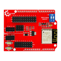
• 1 x 4 Screw Terminal (Motor Control)
• Motor A Positive Lead
• Motor A Negative Lead
• Motor B Positive Lead
• Motor B Negative Lead
These motor connection points are also mirrored on a 4-pin female header for a little more flexibility.
These motor drive leads also have yellow and green LEDs attached to them. Their brightness will vary
depending on the strength of the PWM signal
• 1 x 4 Female Header (Black)
• MA = Motor A connection (x2)
• MB = Motor B connection (x2)
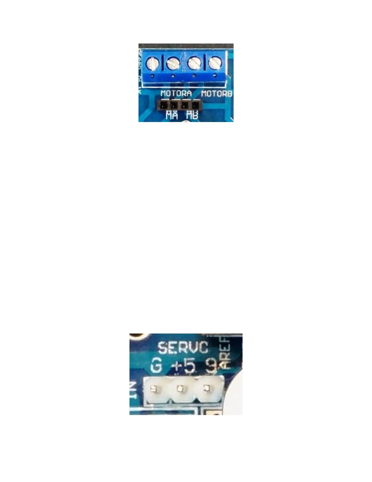
Servo Motor Connections
Servo motors are 3 wire devices. They require 5V, Ground and a PWM signal to set its position. The shield
uses D9 for the PWM signal. One nice feature of these modules is that it has a dedicated 5V regulator to
power the servo to prevent electrical noise from getting back into the main 5V logic power.
Servos are typically used to turn a small steering wheel or to rotate a sensor, such as an ultrasonic
rangefinder for obstacle avoidance. To use the servo, you will need to have a minimum of 6.3V on the main
motor power connector for the regulator to operate. If you are not using a servo, D9 as well as this dedicated
5V is available for other uses.
 Loading...