• 1 x 3 Servo Header (White)
• G = Ground
• +5V = Dedicated 5V for powering servo motor
• 9 = D9 is the PWM pin that the servo is driven off. This pin is available for other use if not using
it to drive a servo motor.
Arduino to Shield Pin Connections
All of the I/O is brought up to stackable female headers on the shield except for the IOREF and the two I2C
pins hear the USB connector so it can support a daughter shield as long as it does not conflict with the pins
in use. In addition, many of these pins are broken out to other headers for easy hookup.
The shield uses the following pins which remain available if you are not using that function:
• Ultrasonic Sensor Ping Control = D7, D8
• Servo motor control = D9
• DC motor control = D10,D11, D12, D13
• Buzzer = D4
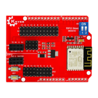
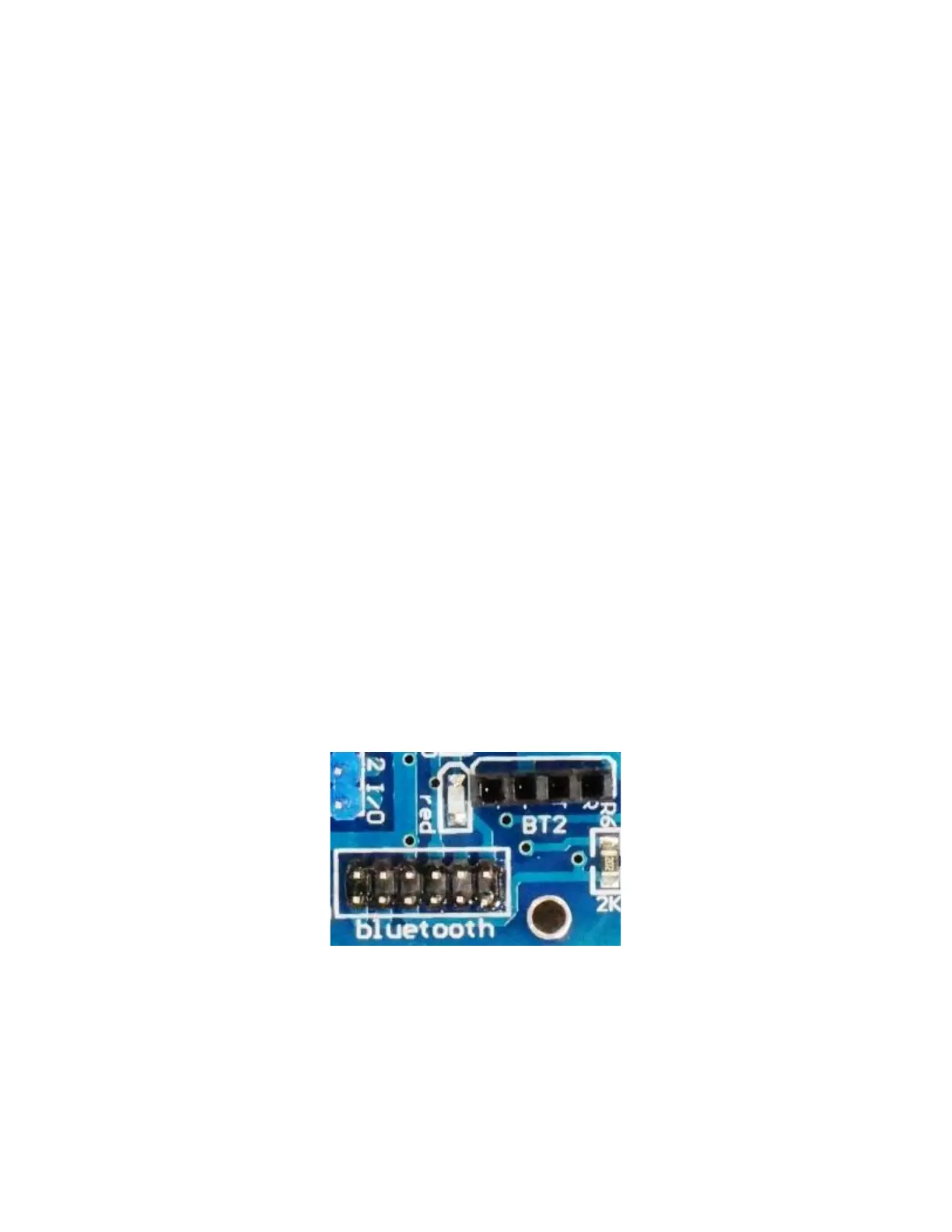
• Bluetooth
There are two Bluetooth connectors on the board
The first connector is a 4-pin header that brings out 3.3V power, ground, TX, and RX. This type of
connector is compatible with HC-06 Bluetooth modules and perhaps some others. The Receive pin has a
1K/2K voltage divider to level shift the TX output of the Arduino to be 3.3V compatible which is a nice
feature.
• 1 x 4 Bluetooth ‘BT2’ Female Header (Black)
• ‘+‘ = 3.3V
• ‘–‘ = Ground
• T = D0 (RX)
• R = D1 (TX)
 Loading...