9
two servos, and an electronic speed control (ESC). When the transmitter
nds this unit and pairs with it, the unit will instruct the elevator and
rudder control surfaces to move to indicate that the pairing process is
complete and that the motor is now armed. When this happens, follow your
transmitter’s instruction manual for guidance on exiting the pairing process.
Having paired your transmitter the Sopwith’s 3-in-1 control unit will now
recognise the Globally Unique Identier (GUID) code of your transmitter and
will automatically pair with it whenever you switch on and connect the ight
battery.
Note: If you have servo movement but the motor is not working, unplug
the ight battery, check that the throttle stick is at its lowest position, then
re-plug in the ight battery. This should re-initialize and arm the electronic
speed control.
3. Flight controls. Check the control surfaces, as below, noting that
instructions for servo reversing are given on page ?? of this manual. Note,
also, that on this 3-channel airplane the rudder function is controlled by the
aileron stick on the transmitter. The pushrod for the elevator should be in
the outermost hole on the control horn while the rudder pushrod should be
in the hole before the outermost hole.
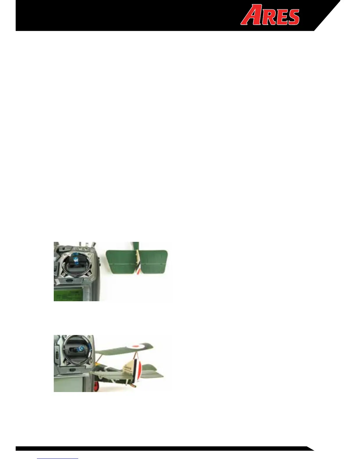
With the model in front of you, facing away, move the rudder stick to the
right and check that the rudder moves right in response. Left rudder stick
will move the rudder to the left.
Pull the elevator stick back and check that the elevator moves in an upward
direction. Push the elevator stick forward and check that the elevator moves
in a downward direction.
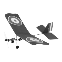
With the propeller clear of obstructions and the model restrained, open the
throttle slowly and check that it turns in an anticlockwise direction, when
viewed from the front.