28
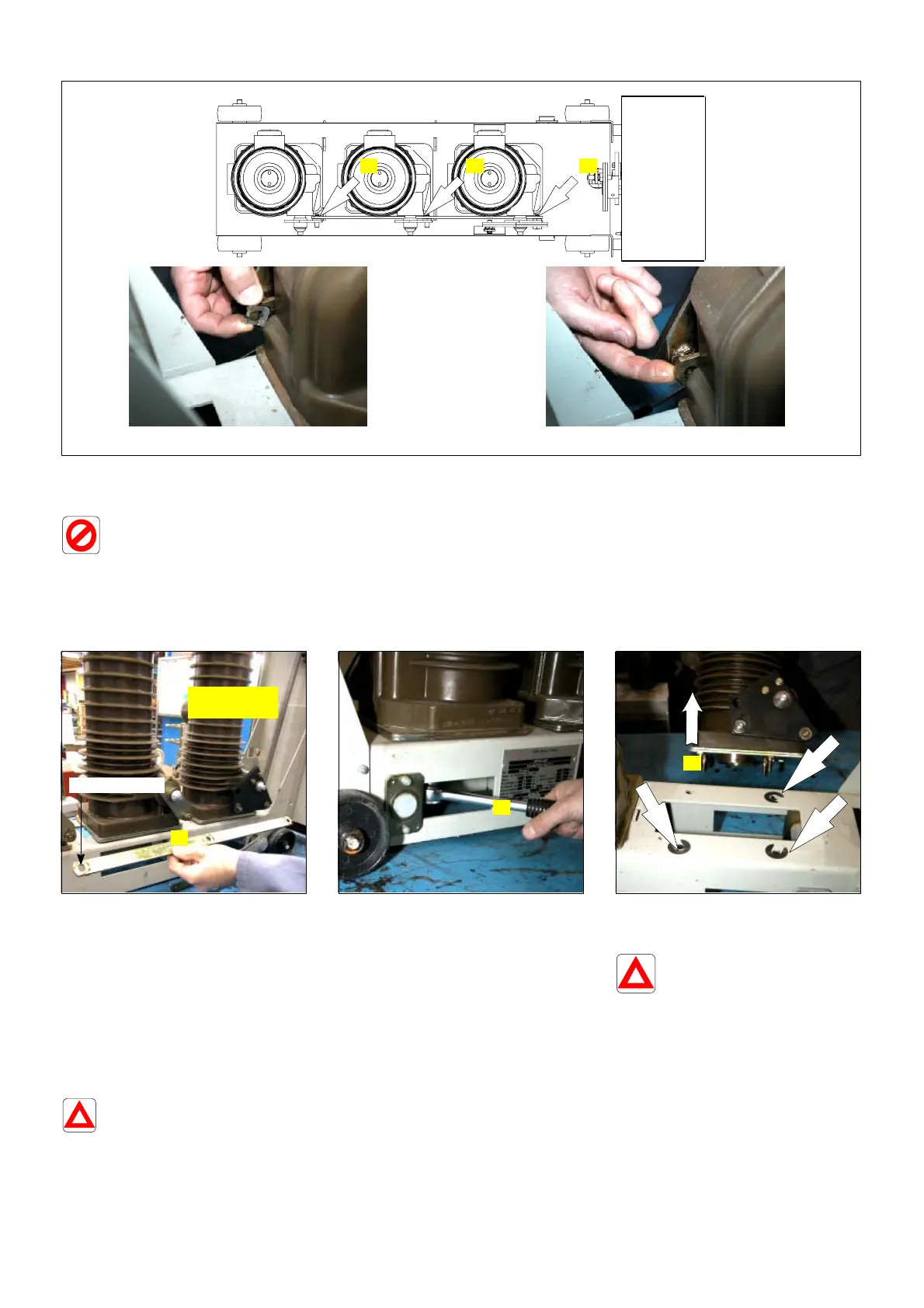
3 - Remove the 3 clamps from the
poles' drive rod.
Release this rod.
The poles' levers absolutely must
remain in their
initial position
L 1L 2L 3
Unclamp Release
3 3 3
Top view
4 - Remove the poles' drive rod.
Note down its position: the
oblong hole is opposite the
leading pole.
Oblong hole
Leading"
pole
4
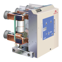
5 - Unscrew the 4 nuts fixing
the pole on to the frame
(access is by the slots on both
sides of the frame, 16 or 17mm
spanner).
5
6 - Remove the pole from the
frame and lay it on its side, on
an anti-shock protection mat.
Leave in place any possible
shimming washers
on the frame.
6
10.6 Removal of the drive lever plate on the pole
The drive levers have several
bore sizes (multiple uses).
Before dismantling, if the pole
crank handles are equipped with a
means of foolproofing, it is not
necessary to make a note of the
pin holes.
If the contrary is the case, you
absolutely must note down
precisely as possible the position of
the pins on the drive plate.