32
10.10 Re-assembly of the equipment
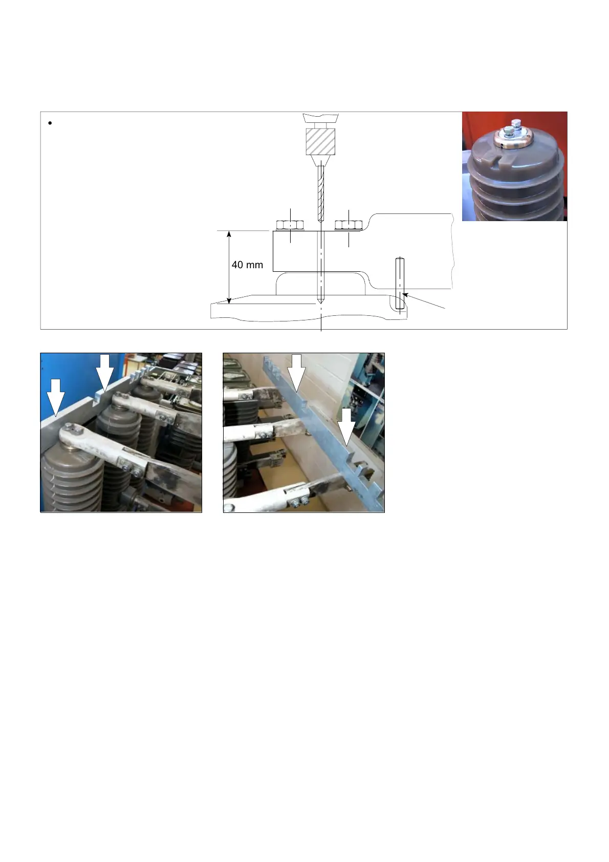
Fitting the upper connector
40 mm
First case: for fitting the cotter pin,
drill a Ø 6 mm H11 hole through the
connector hole:
maximum depth 40 mm.
CAUTION: this operation is not to be
carried out for the second and third
cases, nor for a fixed" circuit breaker.
Close-up of the
power supply
terminal on an
exchange pole
Fit the new 6x35 mm cotter
pin supplied with the
accessories.
Check the presence of the
connector's positioning pin.
Pin
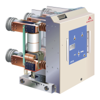
Using a rule, check the
alignment of the replaced pole
in terms of depth, by taking the
two other poles as a reference.
In the same way, realign the
connectors if needed.
Fitting the lower connector
Proceed with operations in the
reverse order to those described in
§ 10.4.