M
Mallory KingJul 28, 2025
What to do if my Ariens Snow Blower will not crank?
- KKevin FernandezJul 28, 2025
If your Ariens Snow Blower will not crank, the suggested solution is to charge the battery or replace it.
What to do if my Ariens Snow Blower will not crank?
If your Ariens Snow Blower will not crank, the suggested solution is to charge the battery or replace it.
| Brand | Ariens |
|---|---|
| Model | 924 SNO-THRO 924108 |
| Category | Snow Blower |
| Language | English |
Explains manual purpose, training, safety, and directional references for the unit.
Guides on ordering parts and locating model/serial numbers for service inquiries.
Details warranty activation through the registration card.
Emphasizes using genuine parts to avoid performance issues and voiding warranty.
Ariens' right to alter products; manual content may differ or be optional.
Outlines different types of technical communications from Ariens.
Identifies and explains safety symbols used throughout the manual.
Explains the meaning of DANGER, WARNING, and CAUTION safety signal words.
Defines the use of NOTE and IMPORTANT notations for information.
Advises on safe working practices and adherence to local laws.
Specifies the necessity of operator training before use.
Stresses proper preparation for service, including work area and tool organization.
Details safe positioning of the unit for maintenance and service.
Provides guidelines for cleaning, preventing corrosion, and storing the unit.
Comprehensive safety rules covering inspection, work area, operation, and general safety.
Safety precautions and limitations for operating on slopes.
Essential safety measures to keep children away from operating equipment.
Guidelines for personal protective equipment and operator alertness.
Safe operation practices for unit controls.
Importance of maintaining the unit in safe operating condition.
Safe storage procedures, particularly regarding fuel.
Critical safety warnings and handling instructions for the unit's battery.
Safe practices for loading, unloading, and securing the unit during transport.
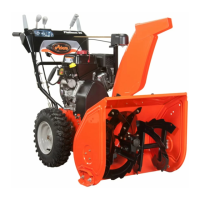
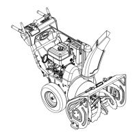
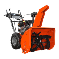
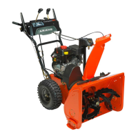
Identifies and illustrates key controls and features of the unit.
Step-by-step procedures for placing the unit in Belt and Upright Service Positions.
Detailed instructions and safety warnings for refueling the unit's fuel tank.
Explains the function and correct positioning of the fuel shut-off valve.
Covers lubrication points, schedules, and recommended lubricants.
Information on maintaining the correct lubricant level in the auger gearcase.
Details on engine cooling, checking oil levels, and changing engine oil.
Instructions and safety warnings for replacing the traction drive belt.
Instructions and safety warnings for replacing the attachment drive belt.
Explains the purpose of shear bolts and provides replacement instructions.
Specifies the maximum recommended tire pressure for the unit.
Covers adjustments for discharge chute deflector, runners, and scraper blade.
Procedure for adjusting the attachment clutch and impeller brake.
Steps to adjust the traction drive clutch for wear compensation.
Procedure for adjusting the speed selector for proper gear shifting.
Instructions for adjusting drive chain tension and checking interlocks.
Procedure for removing and replacing the lower handlebar assembly.
Steps for removing and replacing the attachment clutch handle.
Guide for removing and replacing clutch levers and traction cables.
Instructions for removing and replacing clutch yoke and fork components.
A comprehensive chart to diagnose and resolve engine operational issues.
Detailed steps for safely removing the engine from the unit.
Detailed steps for safely installing the engine onto the unit.
Procedures for servicing the differential axle, lockout hub, and related components.
Instructions for servicing the spur gear drive axle.
Steps for removing and replacing axle bearings.
Guidance on removing and replacing the unit's drive chain.
Procedure for adjusting drive chain tension and checking interlocks.
Steps for replacing the friction wheel assembly.
Instructions for removing and replacing the friction wheel carrier.
Procedure for removing and replacing the drive plate spindle.
Detailed steps for removing the auger and impeller assembly.
How to adjust the scraper blade to compensate for wear.
Information on shear bolts, their function, and replacement procedure.
Instructions for mounting, positioning, and adjusting the discharge chute.
Procedure for installing a new deflector cable assembly.
Guidance on adjusting runners for different surface conditions.
Service procedures for the cast iron gear case, including lubrication.
Service procedures for the aluminum gear case, including bushing replacement.
Diagrams illustrating electrical continuity for key switches and solenoids.
Provides a schematic of the unit's electrical wiring system.