EasyManua.ls Logo

Ariston 3104047 User Manual

Ariston 3104047
44 pages
To Next Page IconTo Next Page
Page #1 background imageLoading...
Page #1 background image
F
DIGITAL CONTROL UNIT
FOR THERMAL SOLAR SYSTEMS
ARISTON - ELIOS 25 - 3104047

Table of Contents

Question and Answer IconNeed help?

Do you have a question about the Ariston 3104047 and is the answer not in the manual?

Ariston 3104047 Specifications

General IconGeneral
BrandAriston
Model3104047
CategoryControl Unit
LanguageEnglish

Summary

TECHNICAL FEATURES

INSTALLATION

VERSION WITH 4 SPST ON-OFF RELAY OUTPUTS, CONTACTS POWERED

VERSION WITH 2 SPST ON-OFF RELAY OUTPUTS + 2 SEMICONDUCTOR RELAY OUTPUTS (VARIABLE COLLECTOR PUMP SPEED), CONTACTS POWERED

STARTING

TEST FUNCTION FOR LOAD WIRINGS CHECK

Details the function for testing wired loads and wiring accuracy via parameter P7.

DISPLAYING TEMPERATURES AND ENERGY PRODUCED

DISPLAY OF COLLECTOR PUMP SPEED

How to view collector pump speed (percentage) on compatible versions.

INSTALLER PARAMETERS

Entering the Password

Details the process of entering the 4-digit password to access installer parameters.

Modifying the Password

Step-by-step guide on how to change the stored password.

Using installer parameters

INSTALLER PARAMETERS: P1-P13

P1: SELECT INSTALLATION TYPE

List of thermal data to be eventually programmed

Lists thermal data parameters like temperatures, differentials, and hysteresis for configuration.

AVAILABLE DIAGRAMS

Control Logic for SCH 01

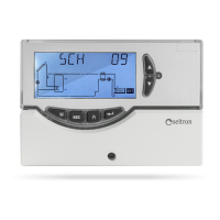
Details the control logic specific to the SCH 01 installation diagram.

SCH 02: Solar heating installation with 1 tank and additional thermostatic heating.

Control Logic for SCH 02

Details the control logic specific to the SCH 02 installation diagram.

SCH 03: Pool solar heating installation.

Control Logic for SCH 03

Details the control logic specific to the SCH 03 installation diagram.

P2: SETTING THE THERMAL DATA

Safety temperatures

Differential

Hysteresis of the safety temperatures

ABC Temperature (Automatic Boiler Control) on probe S3

P3: ANTIFROST PARAMETER MANAGEMENT

WARNING!

Warning about preset antifrost data and qualified personnel for changes.

P4: ACOUSTIC SIGNAL MANAGEMENT

P5: RELAY LOGIC SELECTION

Output logic for OUT 2

P6: INTEGRATION HOURS COUNTER

P7: LOADS WIRING TEST

P8: CALCULATION OF THE ENERGY PRODUCED

P9: RECOOLING FUNCTION

Activation | Deactivation of the Recooling function

WARNING!

Warning about setting Recooling Temperature (TR) equal to or lower than the highest Maximum Temperature.

P10: PERIODIC ACTIVATION OF LOADS

P11: MEASUREMENT UNIT

WARNING

Warning that changing measurement unit resets all stored data to default values.

P12: SETTING OF COLLECTOR PUMP SPEED

MINIMUM SPEED OUT 1 IN %

Sets the minimum speed for OUT 1 in percentage.

MINIMUM SPEED OUT 2 IN %

Sets the minimum speed for OUT 2 in percentage.

P13: MINIMUM TEMPERATURE LIMITATION

Minimum speed OUT 1 in %

Sets the minimum speed for OUT 1 in percentage.

Minimum speed OUT 2 in %

Sets the minimum speed for OUT 2 in percentage.

Adjustment of collector minimum temperature

Enabling/disabling the collector minimum temperature

Enables or disables the collector minimum temperature limitation (MTEN).

FUNCTIONS ACCESSIBLE TO THE USER

USER PARAMETERS

Instructions to access user parameters, including warnings about output disablement.

Displaying the Maximum Temperatures recorded

Antifrost Activation

Automatic Boiler Control by means of Collectors (ABC)

TROUBLESHOOTING

ANOMALY

Describes anomalies like probe errors (open circuit, short circuit) and their display indications.

POSSIBLE CAUSE

Details possible causes for anomalies such as probe open circuits, short circuits, or miswiring.

Related product manuals