Do you have a question about the Ariston ELIOS 25 and is the answer not in the manual?
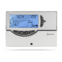
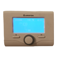
Explains the function of each button on the control unit.
Lists the standards and directives the product complies with.
Lists optional accessories and spare parts for the control unit.
Procedure for assembling the unit with cable input on the rear panel.
Procedure for assembling the unit with cable input on the lower side.
Instructions for making the electrical connections for the installed unit.
Procedure to turn the control unit on and off using the ESC key.
Details on how to activate and the automatic shut-off of the display backlight.
Explains the use of the internal buzzer for feedback on keys, alarms, and failures.
Describes the installer parameter P7 for testing load wirings.
Explains the meaning of 'SUN' and 'SNOW' icons on the display.
Shows collector pump speed percentage for variable speed units.
Describes the three operating modes: Automatic, Manual, and ABC (Automatic Boiler Control).
Procedures for entering and modifying the installer password.
How to navigate and select installer parameters after successful login.
Procedure to select the installation type from available schemes.
Procedure to set thermal data related to the selected installation.
Explains control logic for Manual and ABC operation modes.
Describes the control logic for safety thermostats.
Introduces the hydraulic and control logic diagrams for different configurations.
Diagram and logic for solar heating with one tank and no integrative heat source.
Diagram and logic for pool solar heating installations.
Diagram and logic for solar heating with two tanks, valve logic, and no integrative heat source.
Diagram and logic for solar heating with one tank and solid fuel supplemental heating.
Diagram and logic for East/West solar heating with one tank and no integrative heat source.
Diagram and logic for solar heating with one tank, only two sensors, and supplemental heating excluded.
Procedure to set data for managing the antifrost function.
Procedure to enable or disable acoustic signalling (keyboard tones, alarms, diagnostics).
Procedure to reverse output logic (N.O. to N.C. and vice-versa) for active relays.
Display actual hours of integrative source operation or reset the counter.
Sets up a test for loads and wirings by activating outlets sequentially.
Manages data for measuring heat quantity produced by the plant.
Permits automatic reduction of boiler temperature; indicates activation with 'pump' and 'sun' icons.
Manages periodic activation of loads (pumps, valves) based on hydraulic scheme.
Allows selection of measurement unit, °C or °F, with implications for data reset.
Sets minimum pump speed and temperature variation for collector pump speed adjustment.
Manages the minimum temperature thermostat for collector pump activation.
Allows activation or deactivation of manual operation mode for the installation.
Procedure to access user parameters for limited adjustments.
How to view maximum recorded temperatures for each probe using TMAX U1.
Enables or disables the antifrost function through user parameter U2.
Enables or disables Automatic Boiler Control (ABC) via user parameter U3.
Identifies issues like open circuit or short circuit on probes and their possible causes.
Indicates when probes measure temperature higher than programmed safety limits.
Identifies problems with miswired or damaged probes during installation selection.
| Brand | Ariston |
|---|---|
| Model | ELIOS 25 |
| Category | Control Unit |
| Language | English |