13
WARNING!
When going into parameter P1, the controller will reset
the maximum temperatures (MT) detected until that
moment. Furthermore, when quitting this parameter,
the controller will set again the temperature display
on the sensor S_1.
The thermal parameters to be set are displayed when
the relevant scheme is selected, this means the power
unit will only display the thermal parameters actually
activated for the selected hydraulic scheme.
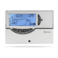
P1: SELECT INSTALLATION TYPE
Pressing the ‘ S ‘ or ‘ T ‘ keys will show all the installations
that can be set up (if the probe for the selected installation
has a problem or is left unconnected that probe will ƀash on
the display). To conſrm the selected installation press the ‘
‘ key; the control unit will memorize the choice and the display
will again show the parameter list.
To cancel the selection press the ‘ esc ’ key. In this case the
control unit will abandon the changes made and will show
again the parameter list.
The parameters inƀuencing the regulation of the selected
setup are listed in the following and can be modiſed through
the second installer parameter (P2).
List of thermal data to be eventually programmed
PARAMETERS DESCRIPTION
TS1-TS2-TS3-TS4 Probe safety temperature
ţT 12 Differential between the probes S1-S2
ţT 13 Differential between the probes S1-S3
ţT 14 Differential between the probes S1-S4
ţT 34 Differential between the probes S3-S4
ţT 42 Differential between the probes S4-S2
ţT 43 Differential between the probes S4-S3
MTC
Adjustment of collector minimum
temperature
MTEN
Enabling/disabling the collector minimum
temperature
TM2 Maximum temperature of the probe S2
TM3 Maximum temperature of the probe S3
TM4 Maximum temperature of the probe S4
TAH Integration temperature on the probe S3
HY12 *ysteresis of ţT 12
HY13 *ysteresis of ţT 13
HY14 *ysteresis of ţT 14
HY34 *ysteresis of ţT 34
HY42 *ysteresis of ţT 42
HY43 *ysteresis of ţT 43
HYT Thermostatic hysteresis
HYTS Safety thermostatic hysteresis
 Loading...