12
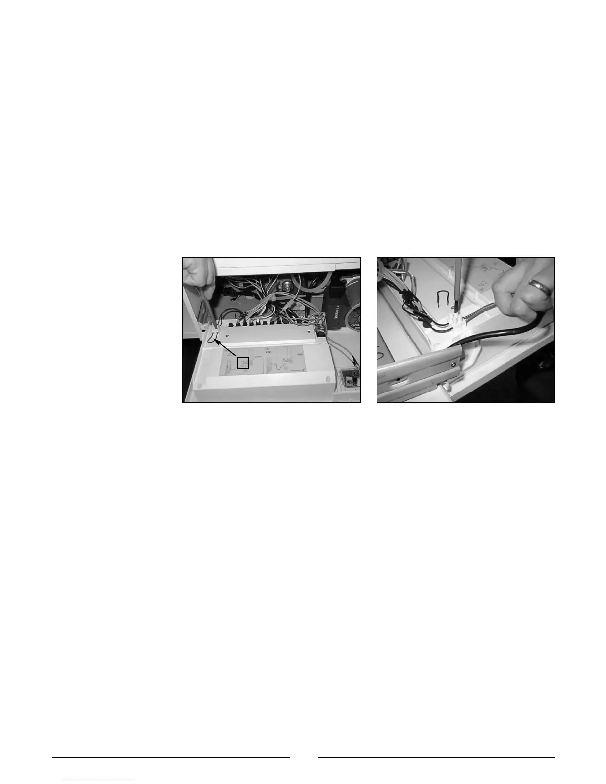
To connect a room thermostat, it is necessary to:
1. - Open the control panel as indicated in section 3.3.
2.- Remove the link
“A” from the terminal block on the reverse of the control panel.
3. - Insert the thermostat cable through the cable grommet and fasten it by means of the
cable-clamp provided.
4. - Then connect the thermostat wires to the terminal block.
5.- If a remote time clock is to be fitted, disconnect the integral time clock from the P.C.B.
6. - Using a volt-free switching time clock, connect the switching wires from the time clock
following points 1-4 above.
7. - If using an external time clock and room thermostat, these must be connected in
series as points 1-7 above.
Note: Only a two-wire type room thermostat can be used.
An anti-frost device is built-in to the appliances electronic regulation
system.
2.10 ROOM THERMOSTAT
CONNECTION
A
2.11 ELECTRICAL/SYSTEM
DIAGRAMS
LEGEND:
A = Central Heating Temperature Adjustment
B = Domestic Hot Water Temperature Adjustment
C = Soft-light Adjustment
D = Maximum Heating Adjustment
E = Time Clock Connector
F = On/Off Switch
G = Fume Sensor L.E.D.
H = Central Heating Selector
I = Ignition Failure (Lockout) L.E.D.
J = On/Off L.E.D.
K = Reset Button
L = Central Heating L.E.D.
M = Transformer
N = Circulation Pump Relay
O = Fan Relay
P = Gas Valve Relay
Q = Spark Generator I.C.
A01 = Circulation Pump
A02 = Fan
A03 = Spark Generator/Gas Valve Supply
A04 = Flame Detection Circuit
A05 = Detection Electrode
A06 = Main Circuit Temperature Probe
A07 = Domestic Hot Water Temperature Probe
A08 = D.H.W. Flow switch
A09 = Pump Pressure Switch
A10 = Modulator
A11 = Air Pressure Switch
A12 = Safety Thermostat
A13 = External (Room) Thermostat
Colours:
Gry = Grey
Wh = White
Pnk = Pink
Brn = Brown
Bl = Blue
Blk = Black
Rd/Blk = Red/Black
FO016A
FO017A

 Loading...