Do you have a question about the Ariston microGENUS 23 MFFI and is the answer not in the manual?
This document provides comprehensive servicing instructions for the Ariston Micro Genus Type C Boilers, specifically models with G.C.N. 47-116-14 and 47-116-15. It is intended for competent persons performing annual maintenance and repair, and should be left with the end-user for reference. The manual outlines procedures for gaining general access to the boiler's internal components, accessing the combustion chamber, servicing and removing the gas valve, accessing the water circuit, and interacting with the control system. Additionally, it includes a detailed fault-finding guide, electrical diagrams, and a short spare parts list to assist with troubleshooting and repairs.
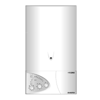
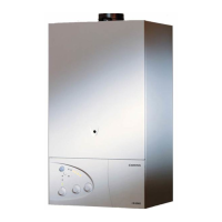
The Ariston Micro Genus Type C Boilers are designed to provide central heating and domestic hot water. These boilers are equipped with various components that work in conjunction to ensure efficient and safe operation. The core function involves igniting gas to heat water, which is then circulated through the heating system or supplied as hot water for domestic use. The boiler incorporates a sealed combustion chamber, a main heat exchanger, a fan for flue gas extraction, and a gas valve to regulate gas flow and pressure. The water circuit includes a D.H.W. (secondary) exchanger for hot water production, a safety valve, an automatic air vent, a main circuit flow switch, a pump for water circulation, a pressure gauge, and an expansion vessel to manage system pressure. Control is managed by a Printed Circuit Board (P.C.B.) which interacts with various sensors, including heating and D.H.W. temperature sensors (N.T.C.), an overheat thermostat, and a divertor valve actuator to manage water flow.
While this manual focuses on servicing, understanding the usage features is crucial for effective maintenance. The boiler's operation is controlled via an On/Off button and a "summer/winter" switch, allowing users to select the desired mode of operation. The heating thermostat knob adjusts the heating circuit power. For domestic hot water, the boiler activates when a hot water tap is turned on, and the flow rate influences the main burner's operation. The boiler also includes an electronic anti-frost device, which activates if the heating temperature drops below 5°C, protecting the system from freezing. The control panel, which can be lowered for servicing, provides access to these user-facing controls. The fault-finding guide in the manual helps diagnose issues that might arise during normal operation, such as the pump not running, the "no water" L.E.D. illuminating, or the fan not running, guiding the service person to the root cause.
The manual provides detailed, step-by-step instructions for various maintenance and replacement tasks. Before any servicing, it is imperative to isolate both gas and electrical supplies and ensure the boiler is cool. A combustion analysis should be performed before and after servicing using the flue sampling point. Preliminary electrical system checks (polarity, earth continuity, resistance to earth, and short circuit) are also required after servicing to ensure safety.
General access involves:
Accessing the combustion chamber involves:
Servicing and removal of the gas valve includes:
Accessing the water circuit requires draining the boiler and involves:
Accessing the control system involves:
The fault-finding guide uses flow-charts to systematically diagnose issues based on symptoms like power L.E.D. status, pump operation, "no water" L.E.D. illumination, fan operation, air pressure switch activation, flue discharge, burner ignition, and boiler safety shutdown. This structured approach helps service personnel efficiently identify the faulty component. Electrical diagrams provide a visual representation of the boiler's wiring, aiding in electrical troubleshooting. The spare parts list, categorized by key number and G.C. part number, facilitates easy identification and ordering of replacement components.
| Model | microGENUS 23 MFFI |
|---|---|
| Mounting | Wall-mounted |
| Fuel Type | Natural Gas |
| Output | 23 kW |
| DHW Output | 23 kW |
| Efficiency Class | A |
| ERP Rating | A |
| Max working pressure | 3 bar |
| Flow rate at 35°C ΔT | 9.8 l/min |
| NOx emissions | Class 5 |
| Ignition | Electronic |
| Warranty | 2 years |
| Control | Digital |