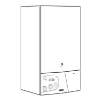
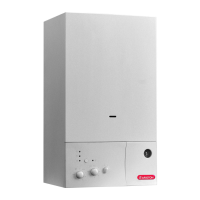
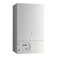
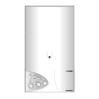
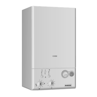
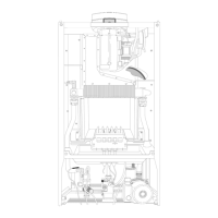
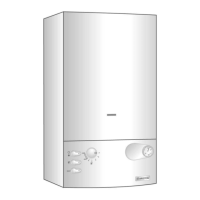
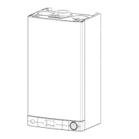
LEGEND:
A -
On/Off Button
B - Domestic Hot Water Temperature Adjustment
C - Central Heating Temperature Adjustment
D - Reset Button/Flue Test analysis mode*
E - Comfort Mode Selector
F - Summer Mode LED (Green)
G -
Ignition/Overheat Lockout LED (Red)
H - Central Heating (Winter Mode) LED (Green)
I - Digital Display (Fault Code/Water Temperature)
J - Time Clock
K- Central Heating System Pressure Gauge
2.10 CONTROL PANEL
FIG. 2.22
FR020A
* Warning the flue analysis mode must only be selected by a
qualified service engineer.
DISPLAY CAUSE
A
A
0
0
1
1
No flame after safety time (7 seconds)
A
A
0
0
3
3
The heating flow temperature exceeds
103
o
C during operation
A
A
9
9
7
7
Problem with the electronic monitoring
A
A
9
9
8
8
Problem with the electronic monitoring
A
A
9
9
9
9
Problem with the electronic monitoring
E
E
0
0
2
2
Insufficient water pressure
E
E
0
0
4
4
Domestic hot water temperature probe in
open circuit
E
E
0
0
5
5
Domestic hot water temperature probe
short circuited
E
E
0
0
6
6
Heating flow temperature probe in open
circuit
E
E
0
0
7
7
Heating flow temperature probe short
circuited
E
E
0
0
8
8
Heating return temperature probe in open
circuit
E
E
0
0
9
9
Heating return temperature probe short
circuited
E
E
2
2
0
0
Flame detected with gas valve closed
E
E
2
2
1
1
Error in the electrical connection (live and
neutral crossed)
E
E
3
3
3
3
The air pressure switch is
closed before the ignition sequence
E
E
3
3
4
4
The air pressure switch does not close
when the fan runs
E
E
9
9
9
9
More than 5 RESETS of the boiler in 15
minutes.
The Control Panel has a 3 digit display, during normal
operation the display will show one of three things on the
tw
o right hand digits;
During Stand-by (no demand for Central Heating or D.H.W.)
‘on’ will be shown on the display and no LEDs will light.
During a demand for Domestic Hot Water, the temperature of
the outgoing hot water is displayed in
o
C (e.g. 38) and the
summer mode LED will light (F - FIG. 2.22).
During a demand for Central Heating, the temperature of the
central heating flow will be displayed in
o
C (e.g. 65) and the
central heating mode LED will light (H - FIG. 2.22).
Dur
ing the oper
ation of the flue analysis mode* the
display will show ‘
sc’.
Should a fault occur the display will show the fault code
and one of two letters, for a non-volatile shutdown the
letter
‘A’
will be sho
wn f
ollo
w
ed b
y the tw
o digit code f
or
the f
ault eg.
‘
A02’
and the red
LED (
G - FIG.
2.22
)
will
light, a non-volatile shutdown will require the reset button
(D - FIG. 2.22) to be pushed before the boiler will attempt
to relight, should the boiler lockout again, the assistance
of an A
uthor
ised Service Engineer should be sought.
Should the boiler develop a fault that cannot be corrected
b
y resetting the boiler
, the letter
‘
E’ will be displa
y
ed
followed by a two digit code (e.g.
E33) indicating a
v
olatile shutdo
wn code
, in the e
v
ent of such a shutdown,
the boiler will automatically resume oper
ation once the
cause behind it is resolv
ed. Should it not the assistance
of an A
uthor
ised Ser
vice Engineer would be required.
A list of the fault codes can be found opposite.
2.11 DIGITIAL DISPLAY AND FAULT CODES

 Loading...
