8
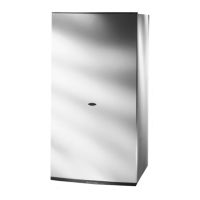
VIEW OF THE BOILER CONNECTIONS
LEGEND:
A = Central Heating Flow
B = Domestic Hot Water Outlet
C = Gas Inlet
D = Domestic Cold Water Inlet
E = Central Heating Return
F = Safety Valve Outlet
G = Drain valve
2.8 WATER CONNECTIONS
2.7 GAS CONNECTION
The local gas region contractor connects the gas meter to
the ser
vice pipe.
If the gas supply for the boiler serves other appliances
ensure that an adequate supply is available both to the
boiler and the other appliances when they are in use at
the same time.
Pipe work must be of an adequate size. Pipes of a
smaller siz
e than the boiler inlet connection should not be
used.
The gas installation should also be in accordance with the
relevant standards. In GB this is BS 6891, and in IE this
is the current edition of I.S. 813.
FIG. 2.4
F
IG. 2.5
KT007A
CENTRAL HEATING
Detailed recommendations are given in BS 6798:1987
and BS 5449-1:1990, the following notes are given for
general guidance.
PIPE WORK:
Copper tubing to BS EN 1057:1996 is recommended for
water pipes
. Jointing should be either with capillary
soldered or compression fittings.
Where possible pipes should have a gradient to ensure
air is carr
ied natur
ally to air release points and w
ater
flows naturally to drain taps.
The appliance has a built-in automatic air release valve,
however it should be ensured as far as possible that the
appliance heat exchanger is not a natural
collecting point for air.
Except where providing useful heat, pipes should be
insulated to pre
vent heat loss and avoid freezing.
Particular attention should be paid to pipes passing
through ventilated spaces in roofs and under floors.
BY-P
ASS
:
The appliance includes an automatic by-pass valve,
which protects the main heat exchanger in case of
reduced or interrupted water circulation through the
heating system, due to the closing of thermostatic valves
or radiators.
SYSTEM DESIGN:
This boiler is suitable only for sealed systems.
DRAIN COCKS:
These must be located in accessible positions to permit
the draining of the whole system and should be fitted at
all low points. The taps must be at least 15mm nominal
siz
e and manufactured in accordance with BS 2870:1980.
SAFETY VAL
VE
DISCHARGE:
A
B
C
D
E
G
F
E
 Loading...