16 /
INSTALLATION
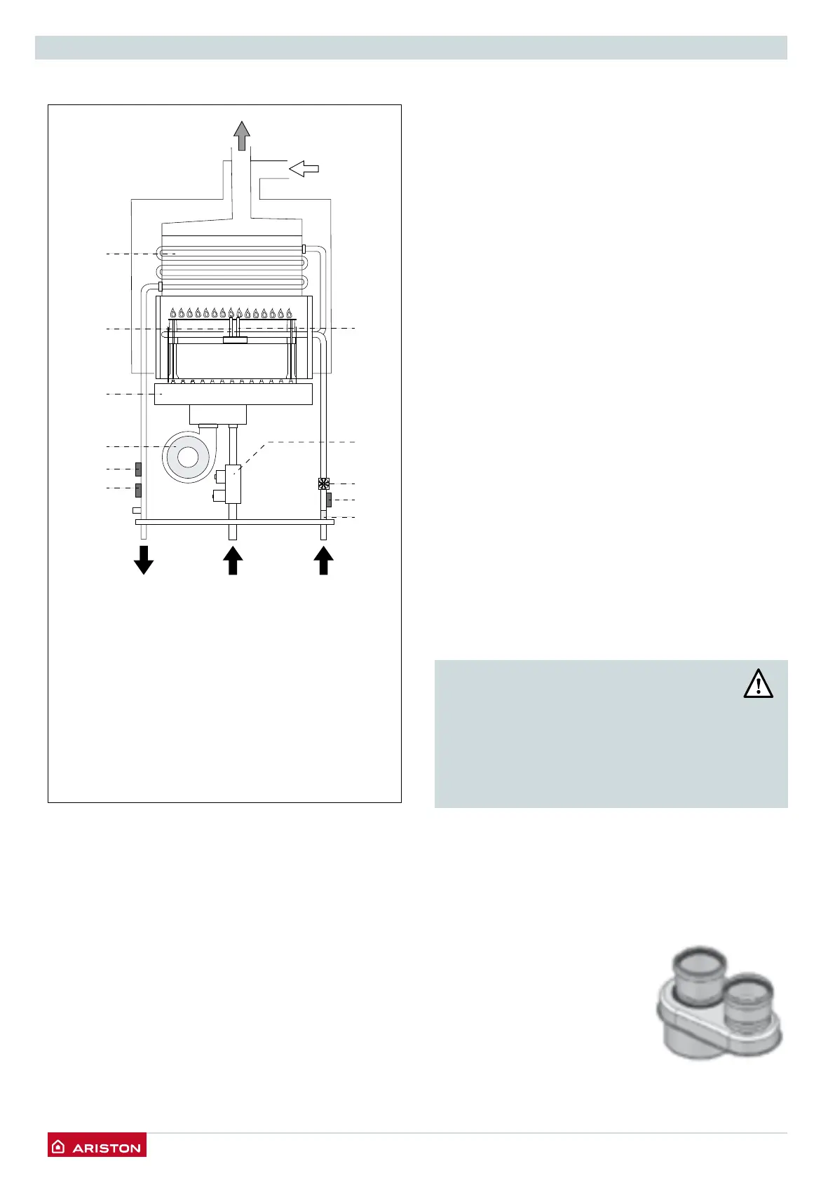
Water circuit diagram
1
2
3
4
5
7
8
10
11
9
6
Key
1. Heat exchanger
2. Detection Electrode
3. Burner
4. Fan
5. Outgoing water temperature sensor
6. Overheat thermostat
7. Cold water inlet lter
8. Inlet water temperature probe
9. Water ow switch
10. Gas valve
11. Ignition electrode
Flue discharge/Air intake duct connections
Intake/discharge ue duct installation must be in
compliance with the regulation in force and instructions
provided by the manufacturer
The appliance is designed to operate in C mode (by
drawing air from outside).
When installing an exhaust system be careful when
handling the seals, in order to avoid ue gas leaking into
the air circuit.
Horizontally-installed piping must have a downward
incline of 3% so as to avoid the build-up of condensate.
When implementing coaxial suction/exhaust systems the
use of authentic accessories is obligatory.
The ue gas exhaust ducting must not be in contact
with or placed near ammable materials, and must not
cross building structures or walls made using ammable
material.
The ue gas exhaust ducting joint should be created using
a male/female coupling and a seal.
Couplings should always be arranged so that they go
against the direction of the condensate ow.
For the calculation method, equivalent length values
and installation examples please refer to the gas ue
accessories catalogue.
The suction/exhaust ducting connection kits are supplied
separately from the appliance, according to different
installation solutions. Carefully read the instructions in
the kit.
If there is any loss of pressure in the piping, please refer
to the gas ue accessories catalogue. Supplementary
resistance must be borne in mind during the sizing
process mentioned above.
WARNING
MAKE SURE THAT THE FLUE GAS EXHAUST
AND VENTILATION DUCTING ARE NOT
OBSTRUCTED.
MAKE SURE THAT THERE ARE NO LEAKS
ALONG THE FLUE GAS EXHAUST DUCTING.
The appliance is set up for connection to a coaxial suction
and ue gas exhaust ducting system (60/100).
The appliance is set up for connection to a 60/100 coaxial
air intake and ue gas exhaust ducting ystem.
For split types of suction and exhaust, using the specied
adapter.
 Loading...