11
installation
EN
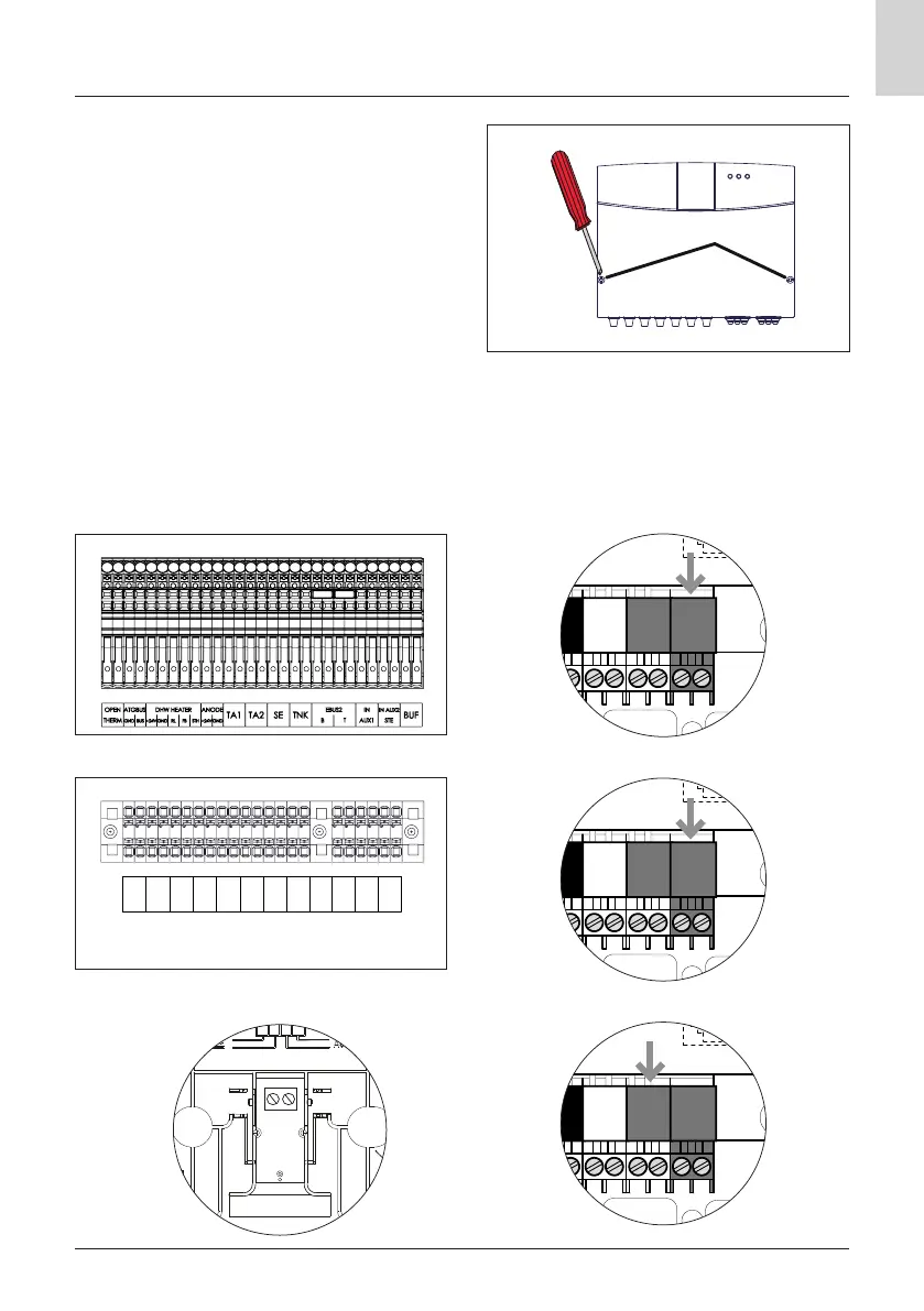
Electric connection of the module
WARNING
Before carrying out any work, disconnect
the power supply through the external
bipolar switch.
To access the kit's terminal block, proceed as
follows:
– remove the module's front panel,
– remove the control unit cover by loosening
the two front screws (b),
– connect the BridgNet® BUS connector and
check the polarity of the connection: T with
T, B with B.
b
A1
AUX1
S1 S2 S3 S4 BUS BUS
B T B T
A1
AUX1
S1 S2 S3 S4 BUS BUS
B T B T
Kit BUS terminal block
Kit BUS terminal block
Kit BUS terminal block
Low-voltage terminal block Heat pump
Low-voltage terminal block Hybrid
System interface terminal block
A1
AUX1
S1 S2 S3 S4 BUS BUS
B T B T
ATGBUS
G S
SE
TNK
B T
IN
AUX1
IN AUX2
STE
BUF
OPEN
THERM
ANODE
+24V GND
TA1 TA2
EBUS