14
preparing the boiler for operation
EN
Fault diagnostics guide
The Zone Manager Kit is protected against the risk of faults thanks to internal checks performed by
the board, which stops the system for safety reasons, if required.
The table below indicates the possible fault codes, their description and corresponding corrective
actions:
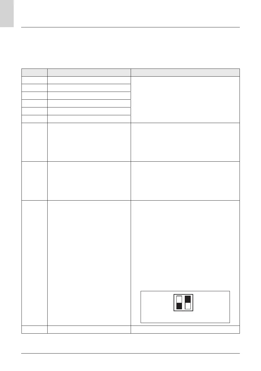
ERROR DESCRIPTION RECOMMENDED ACTIONS
7 0 1 Faulty Z1 delivery sensor
Check the connection of the relative probe.
Check the continuity of the probe.
Replace the probe if necessary.
7 0 2 Faulty Z2 delivery probe
7 0 3 Faulty Z3 ow probe
7 1 1 Faulty Z1 return probe
7 1 2 Faulty Z2 return probe
7 1 3 Faulty Z3 return probe
7 2 2 Zone 2 overheating
Check whether the shunt is present and whether
it is connected to terminal block “ST2” of the box,
or check the maximum heating temperature
adjustment for Zone 2 (parameter 525). Check the
connection of the safety thermostat on terminal
block “ST2” of the box.
7 2 3 Zone 3 overheating
Check whether the shunt is present and whether
it is connected to terminal block “ST3” of the box,
or check the maximum heating temperature
adjustment for Zone 2 (parameter 625). Check the
connection of the safety thermostat on terminal
block “ST3” of the box.
4 2 0
Power supply overload
BridgeNet® BUS
A BUS power supply overload error may occur due to
the connection of three or more devices within the
installed system.
Devices which may overload the BUS network in-
clude:
– Multi-zone module
– Energy Manager hybrid system or heat pump
– Solar pump assembly
– Module for instantaneous domestic hot water
production
To avoid overloading the BUS power supply,
set microswitch 1 on one of the PCBs inside the
equipment connected to the system (except the
boiler and energy manager) to OFF.
1
ON
OFF
2
microswitch
7 5 0 MZ hydraulic diagram not dened Refer to the “Programming” paragraph.
Temperature adjustment
For the temperature adjustment function consult the heating/cooling system installation manual.
 Loading...