3
CAMERA FUNCTIONS AND SWITCHES
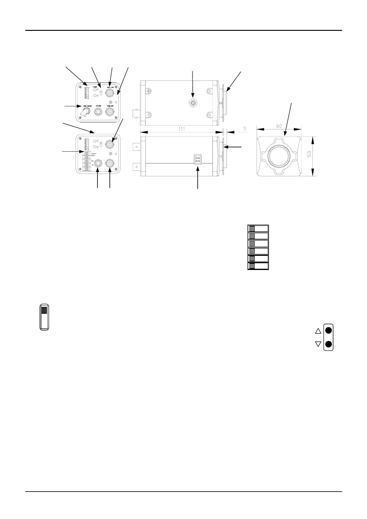
Some features may vary depending on the model. All measurements are in mm
A. C (CS) mount adapter
If using a CS lens, remove the C mount ring.
B. Back focus adjustment.
Unscrew the Back Focus locking screw. Turn the ring to
optimise focus. (B&D)
C. Camera mounting points.
Standard photographic pan-head bolt with a 1/4” BSW or 20
UNC thread.
D. Back focus adjustment locking screw (B&D)
E. Auto-iris and direct drive lens connector (MINI JACK).
See section “Auto-iris lens connector” below
F. Red power LED
G. Monitor output socket (BNC).
Second video output connection (1V peak to peak)
H. Lens mode switch
DD: For direct drive lenses
VD: For video drive auto-iris lenses
AES: For fixed/manual iris lenses
I. DC level adjustment.
When using a direct drive (DD) lens, adjust the lens level
potentiometer to obtain the correct light exposure.
J. SW1
Auto Tracking White Balance
Auto Backlight Compensation ON/OFF
Normal AGC / Super AGC
GAMMA 0.45 / 1 (default 0.45)
Line-Lock / Internal sync
No connection
Conventional auto white balance
K. External synchronised phase adjusting button
to adjust line-lock phase (Line-lock model). See
figure on right.
L. AC85V~265V power cord
M. DC 12V or AC24V/DC12V terminal block
N. Video output socket (BNC)
Main video output connection (1 Vpeak-to- peak)
O. Y/C output S-terminal
For Y/C output connection
Y: 1 Vp-p and C: 0.3 Vp-p at 75 Ohm load
ATW
BLC
N AGC
r=.45
LINE LOCK
WB
BLCOFF
SUPERAGC
r= 1
INT
NC
0 1
VD
A
N
VIDEO OUT
DD LEVEL
MONI. OUT
INTLINE LOCK
S-VIDEO
NC
NAGC
r=.45
ATW
BLC
PHASE
BLCOFF
SUPERAGC
r=1
AWB
DD
AES
VD
POWER
BLC
ATW
r=.45
NAGC
LINE LOCK
NC
r=1
SUPERAGC
BLCOFF
INT
VD
AES
DD
AWB
DD LEVEL
POWER
B
C
D
FG
H
J
L
K
M
I
O
E