Do you have a question about the Aritech ATS7340 and is the answer not in the manual?
Explains the functionality of the ATS7340 4G module for ATSx500A Advisor Advanced panels, including reporting formats.
Details on using the ATS7340-SIM with UltraSync functionality and SIM card usage policies.
Step-by-step guide for connecting the flat cable, antenna, and inserting the SIM card for the 4G module.
Instructions for selecting the mounting location and physically installing the ATS7340 into ATSx500A panels.
Procedure to verify correct reporting to the Central Station by creating and confirming test events.
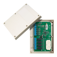
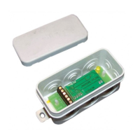
Details on the ATS7340 components including DIP switch, LEDs, connectors, and SIM socket.
Explains the MI_ST (communication interface) and RSSI (signal strength) LED indicators and their meanings.
Describes the function of NET, DATA, CALL, PSUE, SIME, and HB LEDs for network, communication, and system status.
Technical specifications of the ATS7340 module, including compatibility, power, dimensions, and operating frequencies.
Details on product certification, compliance with directives, REACH, WEEE, and links for further documentation.
The ATS7340 4G Module is designed to enable alarm reporting via 2G/3G/4G for the ATSx500A Advisor Advanced panels. This module facilitates comprehensive communication, supporting all reporting formats available through PSTN, including voice reporting and audio listen-in. It can serve as either the primary reporting method or as a backup reporting solution, capable of utilizing multiple central stations for enhanced reliability. Furthermore, the ATS7340 is instrumental in establishing a secure and reliable connection for remote uploading and downloading of data to and from the ATS panel, streamlining system management and updates.
For optimal performance and security, several usage features are critical. The module requires the PIN code request on your SIM card to be disabled, which can typically be done via any mobile telephone. It is imperative to use only the supplied antenna with the product, and the antenna itself must be placed outside the control panel to ensure proper signal reception. The antenna should also be mounted at an appropriate distance from people, specifically more than 200 mm, to comply with safety guidelines. For up/downloading via the 4G module, a SIM card with data enabled is necessary. It's important to note that the ATS7340 cannot be connected remotely using the ATS7072 expander kit. Installation of this device must be carried out by a qualified electrician or other suitably trained and qualified person to ensure correct setup and operation. A crucial caution is to ensure that only one GSM/GPRS dialler (ATS7320, ATS7340, TDA7400, TDA7400NG, or ATS7500) is installed on the MI bus to prevent configuration conflicts.
The ATS7340-SIM variant comes with a preinstalled UltraSync SIM card. This module and its SIM card are specifically intended for UltraSync functionality and should only be used when the panel is registered in the UltraSync portal. Registration of the panel in the UltraSync portal is associated with a monthly service cost. Carrier reserves the right to verify that the Carrier SIM card is used in the correct modem; improper use of the modem or SIM card may lead to the product ceasing to operate within the UltraSync infrastructure.
Maintenance and installation procedures are straightforward but require attention to detail. The ATS7340 must be mounted inside an ATS panel housing. Before any work, it is critical to disconnect the mains power by unplugging the AC mains plug from the wall socket or disconnecting the mains using the dedicated circuit breaker. The battery should also be disconnected when applicable. When mounting the ATS7340 into ATSx500A-SM control panels, the process involves removing screws, lifting the control panel PCB, placing extension pillars with plastic rings on existing pillars, placing clips in square holes, mounting the ATS7340 with screws and extension pillars, and finally, placing the ATS control panel PCB back into its original position. For ATSx500A-MM control panels, the procedure is similar, involving placing clips in square holes (using metal pillars if available) and mounting the ATS7340 using screws.
Connecting the 4G module also requires careful steps. After disconnecting the AC mains plug, connect the flat cable between the control panel's MI connector and the ATS7340's CON2 or CON3 connector. The antenna must then be connected to the 4G module; using the provided antenna is recommended for the best signal strength. Insert the SIM module into the SIM socket. Once these connections are made, apply power to both the control panel and the 4G module. To optimize signal strength, check the field strength (RSSI LED) and reposition the antenna if necessary.
Operating instructions and testing are vital for ensuring the module's functionality. For detailed operating instructions, including functionalities, available keys, codes, and user-programmable functions, refer to the ATSx500A Advisor Advanced Installation and Programming Manual. To confirm correct reporting to the Central Station, it is recommended to create an event (e.g., a test call, an opening, or a closing event) and verify that the Central Station successfully receives it.
The device incorporates several LEDs to indicate its status. The MI_ST LED (green) shows the communication interface status. The RSSI LED (green) indicates the 4G module's field strength, with the number of flashes signifying the level. The NET LED (green) displays the network status. The DATA LED (green) indicates the GPRS/LTE communication status. The CALL LED (yellow) shows the audio information transmission status to the central station. The PSUE LED (red) indicates the power supply status. The SIME LED (red) indicates the SIM card status, with flashes indicating specific errors. Finally, the HB LED (red) indicates that the device is running.
Alarm transmission requirements are robust. All 4G module faults are logged in the control panel and indicated by the fault LED and corresponding fault messages on the keypad display. The transmission between central stations and the 4G module is continuously monitored through presence (heartbeat) messages sent to central station receivers. For Advisor Advanced ATSx500A, the required polling time can be programmed in the "Heartbeat time" menu, with values ranging from every second to every day. In dual path reporting scenarios, if the primary CS communication fails, the backup CS heartbeat time automatically switches from normal to frequent, based on a configured value in the "Frequent HB time" menu.
The device also incorporates robust substitution and information security features. It uses Triple-DES symmetric encryption algorithms with a 192-bit key length. If hash functions are used, they provide a minimum of 128 bits of output. Regular automatic key changes are implemented using machine-generated randomized keys, enhancing overall security.
| Model | ATS7340 |
|---|---|
| Type | Control Unit |
| Max Current Output | 1.5 A |
| Partitions | 4 |
| Users | 100 |
| Enclosure Rating | IP30 |
| Communication Protocol | Contact ID |
| Operating Temperature | -10°C to +55°C |
| Number of Zones | 8 |