P/N R466-5641 (EN) • REV B • ISS 27OCT23 3 / 4
Maintenance
The intrusion control panel is only allowed to be serviced by dedicated
service personal. The screw of the housing is intended to protect the
product from unintended use.
For metal housing, the screw is already installed out of the box. For
plastic housing, the screw, available inside housing, should be
mounted before first time use.
To open the housing, remove the housing screw and open the cover.
After the maintenance, replace the cover and fix it with the cover
screw.
Mains power connection
Electrical installation should be carried out by a skilled person.
Solid insulation of the building mains cables should meet the technical
and the environmental specifications of the equipment.
Use the mains connector terminal for connecting the AC mains supply.
A fixed cable or flexible mains lead to earthed mains outlet can be
used. When fixed wiring is used, insert a dedicated all-pole circuit
breaker in the power distribution network. In all cases the mains
connection must comply with local regulations.
Always connect the building protective earthing wire and ensure the
connection is reliable.
In case the panel is connected to the power grid using fixed wiring, it is
recommended that earth wire is longer than line and neutral.
Do connect incoming line and neutral to mains connection block
according to the label. This assures that the line will be protected by
the mains fuse, and that service can be done by service personnel.
Make sure that before connecting the mains power, the mains power
supply is disconnected.
When installing the mains power, use strain reliefs such as cable ties
and coupling PG16s to ensure proper wiring and minimize the risk of
wire damage during installation and use. If product entry hole
breakouts are used, it is required to also make use of UL-V2 (or better)
approved PG16 cable gland. Refer to PG16 specification to meet
minimum and maximum cable diameters.
In all cases local regulations must be observed.
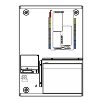
Battery installation and replacement
To install or replace the battery, do the following:
1. Make sure that your product settings allow you to open its cover
without starting the tamper alarm.
2. Make sure that the mains power is off and remove the cover.
3. If necessary, remove the battery shield, unscrewing four screws.
4. If the old battery must be replaced, disconnect the battery. Note
that depending on the battery model the connectors may be
located differently.
5. Remove the battery from the holder.
6. Connect the new battery, sliding the product wires on the wire
connectors. Note that depending on the battery model, the
connectors can be located differently.
7. Mount the battery shield using four screws.
Note: After every battery installation or replacement it is necessary to
set battery capacity in the control panel settings. See Axon x700
Control Panel Installation and Programming Manual for details.
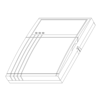
Mounting
The unit is mounted with screws or bolts through the mounting holes in
the rear section of the enclosure.
Important: When the product is mounted to the wall, assure that
at least 3 times the weight of the product can be supported. The
product weight is the product itself plus battery and accessories.
Ensure that the unit is mounted on a flat, solid, vertical surface such
that the base will not flex or warp when the mounting screws and bolts
are tightened.
Leave a 50 mm clearance between equipment enclosures mounted
side by side and 25 mm between the enclosure and the sidewall.
The rechargeable battery must not be fitted until the control panel is
secured to the fixing surface. Under no circumstances should the panel
be transported with a battery fitted.
Cabling
Refer to Axon x700 Control Panel Installation and Programming
Manual for cabling details.
Other manuals
See Axon x700 Control Panel User Guide for more information on how
to use the Axon x700 system.
See Axon x700 Control Panel Manager Manual for more information
on system management.
See Axon x700 Control Panel Installation and Programming Manual for
more information on system configuration and programming.
See SMS Control Reference Manual for more information on SMS
commands.
Specifications
 Loading...