2 / 4 P/N R466-5641 (EN) • REV B • ISS 27OCT23
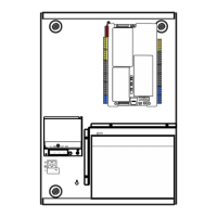
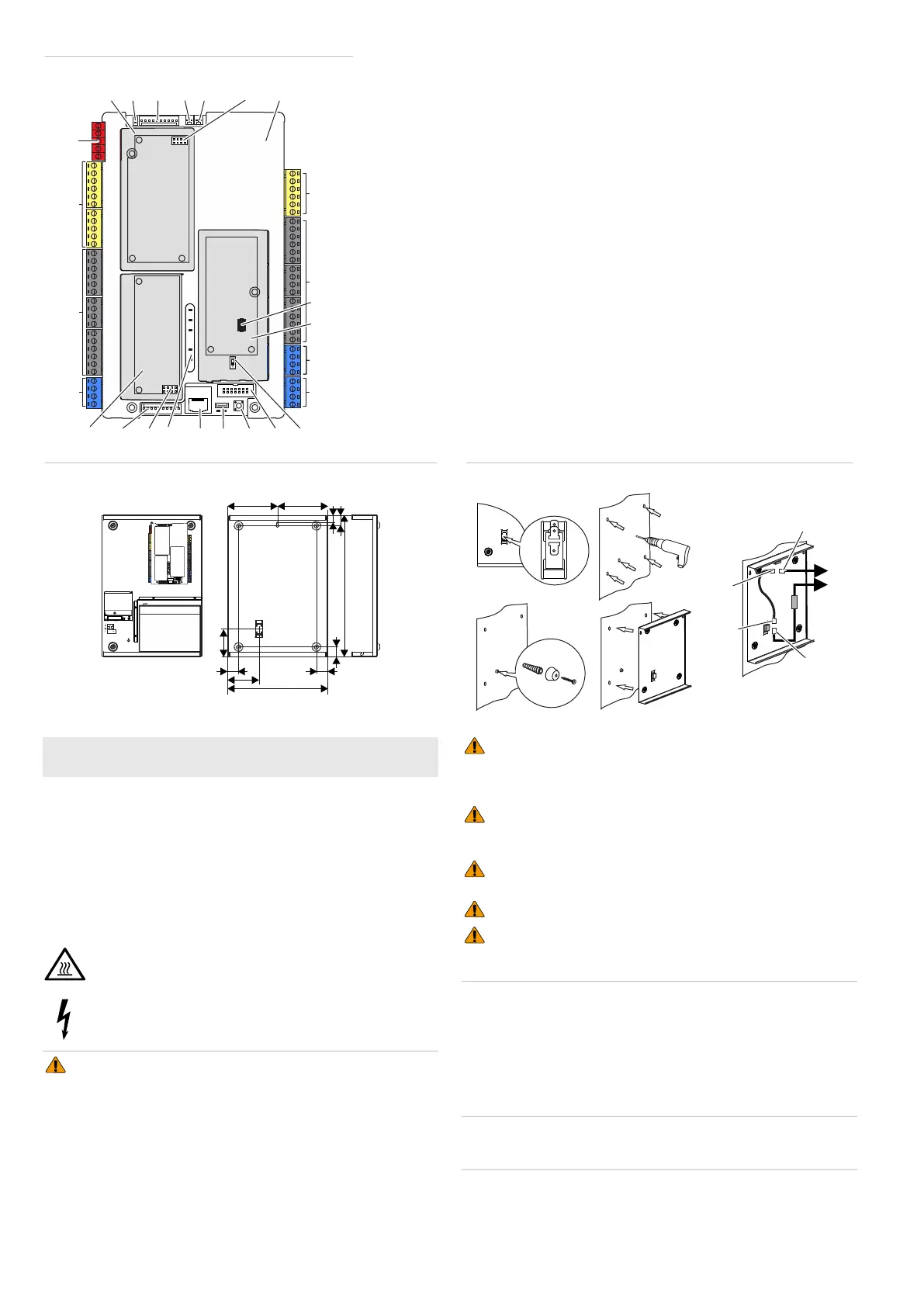
Figure 2: Axon x700 PCB Layout
(1) Tamper contact socket
(2) NTC temperature sensor socket
(3) Legacy output expander interface
(4) Jumper for legacy output expander
(5) Output expander slot
(6) Power supply connector
(7) Siren connection terminals
(8) Zone input terminals (1 to 8) and
auxiliary power
(9) Data bus 1 terminals
(10) Input expander slot
(11) Legacy input expander interface
(12) Input expander interface
(13) LEDs
(14) Ethernet RJ-45 connector
(15) USB connector (micro-A/B type)
(16) PIN bypass push button
(17) MI-bus connector for MI devices
(18) DIP switch
(19) Data bus 2 terminals
(20) Data bus 3 terminals (for future use)
(21) Cellular dialler slot
(22) Interface for add-on module
(23) Zone input terminals (9 to 16) and
auxiliary power
(24) Relay output terminals (1 and 2)
(25) PCB cover
(26) Output expander interface
Note: Not all connectors may be available
in particular Axon x700 panel variants. See
Axon x700 Control Panel Installation and
Programming Manual for details.
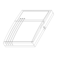
Figure 3: Medium metal housing MM+
Figure 4: Pry-off tamper mount
EN: Quick Installation Guide
This Installation Sheet provides general information on Axon x700
Control Panel installation. For the complete information on control
panel installation and programming, see Axon x700 Control Panel
Installation and Programming Manual.
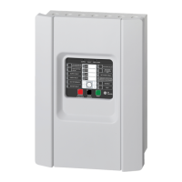
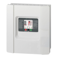
List of panel variants
• ATS1700, ATS3700: Medium metal enclosure MM+
Warnings and cautions
Caution: Hot parts! Risk of burn. Burned fingers when
handling parts. Allow parts to cool down before handling.
WARNING! Dangerous voltage! Risk of injury or death. Fuse
may be in the neutral. The mains should be disconnected to
de-energize the phase conductors.
WARNING! Using incorrect types of batteries may cause risk of
fire, explosion, or chemical leakage. Use only types of batteries listed
in “Specifications” on page 3. Disposal into fire, placing into a hot oven,
leaving in an extremely high temperature surrounding environment,
subjecting to extremely low air pressure, mechanically crushing or
cutting of a battery can result in an explosion or leakage of flammable
liquid or gas.
WARNING! If the housing cover is removed, there is no safeguard
against electrically caused fire that might occur during system
malfunction. The housing cover must be reassembled according to this
installation instruction after each interference by a user.
WARNING: Electrocution hazard. To avoid personal injury or
death from electrocution, remove all sources of power and allow stored
energy to discharge before installing or removing equipment.
WARNING! The battery shield must be mounted during normal
device operation.
WARNING! The correct earthing procedures must be followed.
WARNING! Use cables that comply with IEC 60332-1-2 and IEC
60332-1-3, or IEC 60332-2-2, or IEC TS 60695-11-21, or UL 2556 VW-
1. Use cables and connections that can withstand at least 2 A current.
Axon x700 housing
The housings with mounting holes (items 1) are shown in Figure 3.
Item 2 indicates the pry-off tamper wall stub location.
All dimensions are given in mm.
For pry-off tamper mounting, follow the steps in Figure 4.
Caution: NTC temperature sensor must be mounted close to the
battery and connected to the panel PCB to comply with EN 50131
requirements. The sensor socket is shown in Figure 2 as Item 2.
( )1( )2( )3( )4
( )6
( )7
( )5
( )8
( )9
( )11( )10 ( )13 ( )14 ( )15 ( )16 ( )17 ( )18
( )19
( )20
( )23
( )24
( )25
(12)
( )21
( )22
( )26
35
315
90
31
33
24
445
35
97.5
157.5157.5
( )1
( )1 ( )1
( )1( )1
( )2
1 2 3 4 5
L N −V +V
COM
NO
COM
NO
CT
TAMPER
(B)
(C)
(D)
(E)
(A)
 Loading...