5
Rate of feed
The rate at which the router is moved through the
material has a significant effect on the quality of the
cut and the length of service you will get from your
router and bits. Moving the router through the cut
too fast, as well as possibly overloading the tool and
damaging the bit, will cause the bit to take larger
pieces of material with each rotation, thereby causing
a rough, uneven cut. Moving the router through the
cut too slowly tends to cause burning of timber and
if excessive, will cause overheating of the bit.
The proper feed rate to use depends on the bit size,
the material being cut, the depth of cut and the speed
selected. With all these variables the surest way to
ensure that you get the best quality and efficiency of
cut is to practice on a scrap piece of the same
material to get a feel for what feed rate to use. This
will also show you exactly how the cut will look and
allow you to check your cutting depth.
Straight guide
1. The straight guide is used for chamfering, grooving
and straight cuts.
2. Always ensure that the straight guide is installed
on the right hand side in the feed direction
(Ref fig. 8).
3. To install, line up the holes in the tool base and
slide in the guide bars of the guide. Set the bit
and the straight guide at the desired position then
tighten the support screws.
4. When cutting ensure the straight guide sits flush
with the side of the workpiece. If the side of the
work piece is not straight the straight guide
cannot be used (fig. 9).
5. If the edge is too far away for the straight guide
to reach whilst still keeping the poles retained in
the base, or there is not a straight edge to follow,
a piece of wood or other straight material can be
clamped alongside where the cut is to be made.
The straight edges of the base can then be used
to guide the router instead of the straight guide.
4
4. The stopper block has three adjusting positions.
You can easily obtain three different depths of
cut without adjusting the depth adjustment pole.
Starting the tool
1. To start the tool simply press in the operating
switch firmly during operation (fig. 4).
2. To stop the tool simply release the switch.
3. The following is a guide to suitable speed settings
for different applications. These are indicative
only, and will depend on the actual material and
cutter. It is advisable to make some test cuts on a
scrap piece of material before routing the actual
workpiece.
Variable speed control
1. The router is equipped with variable speed
control for greater flexibility of operation. It is
recommended that the speed dial be preset prior
to operation.
2. To adjust the speed simple turn the dial (fig. 5) until
the desired speed is reached (9,000 to 27,000 rpm).
’A’ indicates the lowest speed while ’G’ indicates
the highest speed.
Setting the depth of cut
1. Insert the required bit into the router as outlined
previously.
2. Loosen the wing screw retaining the depth set rod.
3. With the router on a flat surface loosen the lock
lever and lower the router body until the bit just
touches the surface. Tighten the lock lever (Fig. 6).
3. Lower the tool until the tip of the router bit reaches
the desired depth. Engage the lock lever (fig. 6)
and loosen the adjustment screw on the depth
adjustment pole and let it fall freely until it makes
contact with stopper block. Then tighten the depth
adjustment screw (fig. 3).
Speed
Control
Dial
Fig. 3
Fig. 5
Fig. 4
Material
Hardwood
(Ash, Oak,
Jarrah, etc)
Softwood
(Pine, etc)
Chipboard
and MDF
Router Bit
Diameter
4-10mm
10-20mm
20-40mm
4-10mm
10-20mm
20-40mm
4-10mm
10-20mm
20-40mm
Approx.
Speed Setting
F-G(Max)
D-E
A-C
E-G (Max)
D-G (Max)
B-D
D-G (Max)
C-E
B-D
4. Lift up the depth set rod and rotate the triple depth
stop block to a suitable detent position.
5. Allow the depth set rod to rest on the threaded
bolt in the triple depth stop block and note the
scale reading where it enters the upper housing.
6. Add the required depth of cut to the scale reading
(in mm), move the depth set rod up to this reading
and tighten the depth set rod retaining screw. The
router is now set for the required depth.
NOTE: Always do a trial run of a new set depth on
a scap piece of material to ensure the depth of cut
is exactly as required.
7. If making a deep cut it is advisable to make more
than one pass to achieve the desired depth. The
depth of cut achievable with each pass depends
greatly on the size of the bit and the material
being worked, but no cut irrespective of bit size
Lock Lever
Fig. 6
should exceed 15mm. Excessive depth of cut will
unduly labour the motor, place excessive strain on
the bit, make the router more difficult to control
and significantly reduce the quality of the cut
being made.
8 The triple depth stop block can be used to assist
in making multiple passes, particularly when
working on more than one piece of material. If the
final depth of cut is set using the shortest of the
three threaded studs the two longer studs can be
set to two appropriately shallower depths. Using
the block in this way removes the necessity for
resetting the depth set rod for each pass.
Routing
1. Be sure the workpiece is clamped or otherwise
firmly secured.
2. Switch on the router and allow the motor to come
up to the full selected speed.
3. Plunge the bit down into the workpiece to the set
depth and lock it in place with the lock lever.
4. Holding the tool firmly with both hands progress
smoothly through the cut until complete.
5. Release the lock lever and allow the bit to come
free of the workpiece before removing the router.
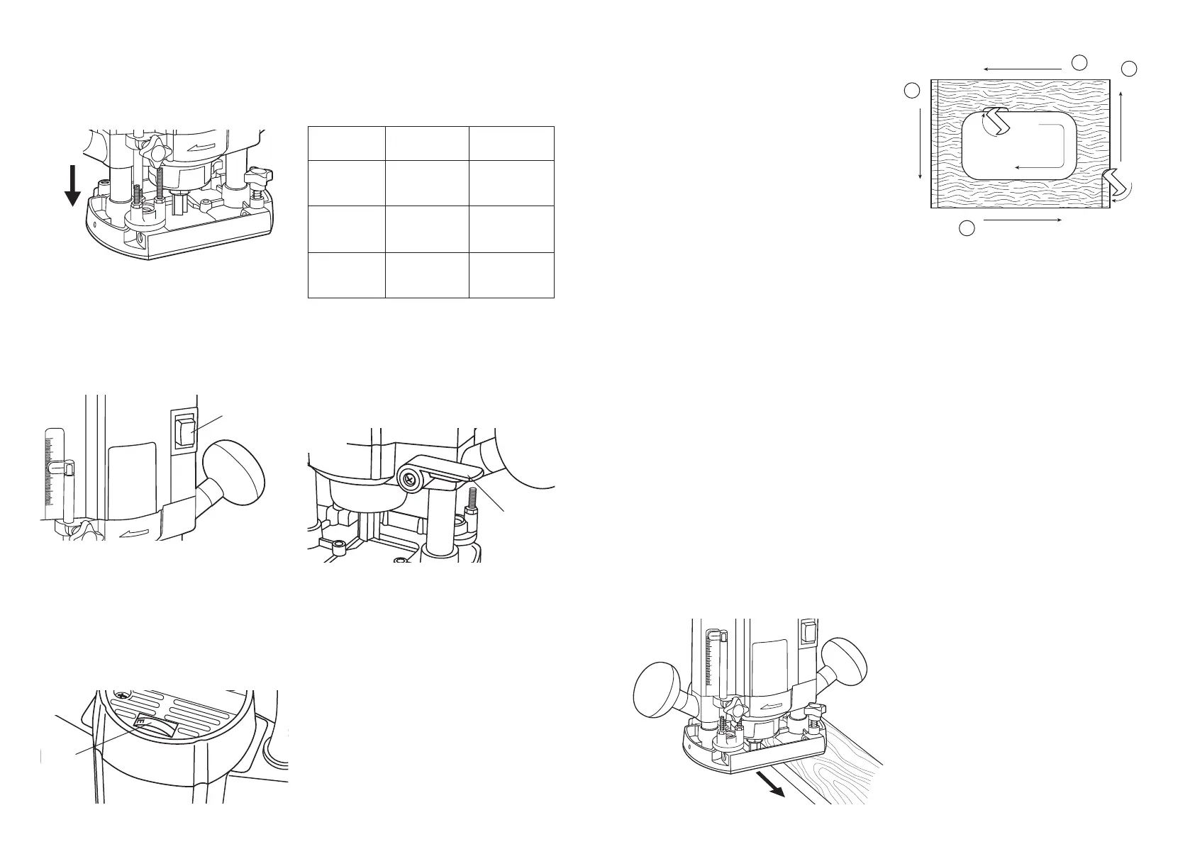
Direction of feed
The router motor, and therefore the bit, revolves in a
clockwise direction. This gives the tool a tendency to
twist counter clockwise in your hands, particularly
when starting the tool. The router bits are all
designed to use this clockwise rotation to assist in
the cutting and clearing of the material. Therefore
when using the router it should always be moved
from left to right as you are facing the workpiece
(Fig. 7). When cutting edges, move the router anti-
clockwise for outside edges and clockwise when
cutting inside edges. The diagram (Fig. 8) shows the
proper feed directions as viewed from the machine
side.
NOTE: Also the preferred sequence of outer edge
cuts when routing a board.
 Loading...