EasyManua.ls Logo

ARO 67151-*-*11 series User Manual

Default Icon
4 pages
To Next Page IconTo Next Page
Page #1 background imageLoading...
Page #1 background image
E2002 D PRINTED IN U.S.A.
& (419) 636-4242 D FAX (419) 633-1674
INGERSOLL-RAND COMPANY
P.O. BOX 151 D ONE ARO CENTER D BRYAN, OHIO 43506Ć0151
OPERATOR’S MANUAL 67151-X
INCLUDING: SERVICE KITS, DISASSEMBLY / REASSEMBLY, PARTS, TROUBLESHOOTING
ALSO COVERS SERVICE KITS 637176 AND 637228
67151-X-X11 LOWER PUMP END
RELEASED: 10-17-97
REVISED: 9-26-02
(REV. G)
LOWER PUMP END DISASSEMBLY
NOTE: All threads are right hand.
1. Secure the lower pump assembly in a vise, clamping on flats of (13)
pump body.
2. Securely hold (22) suction tube with a strap wrench and unthread
and remove (26) foot valve seat.
3. Remove (25) ball stop pin, releasing (24) ball.
4. Using a strap wrench, unthread and remove (22) suction tube and
(21) washer from (13) pump body.
5. Push (1) piston rod and components out thru the bottom end of (13)
pump body. NOTE: Be careful not to damage the finish on (1) piston
rod.
6. Unthread and remove (20) inner check seat, releasing (19) ball, (18)
washer and (17) cup.
7. Unthread and remove (3) spacer tube and (5) solvent cup from (13)
pump body, releasing (12) washer, (11) spring, (8 and 9) V" packĆ
ings, (7) female packing washer and (6) washer.
8. Unthread and remove (5) solvent cup from (3) spacer tube and reĆ
move (4) O" ring.
9. Unthread and remove (14) piston rod from (1) piston rod.
10. Loosen (15) nut and unthread and remove (16) cup follower from
(14) piston rod.
LOWER PUMP END ASSEMBLY
NOTE: Thoroughly clean and lubricate all seals. Replace all soft
parts with new ones included in the repair kit. Note: Refer to the ilĆ
lustration (figure 2, page 2) for V" packing lip direction.
1. Assemble (4) O" ring to groove in (3) spacer tube and assemble (5)
solvent cup to (3) spacer tube.
2. Assemble (6) washer, (7) female packing washer, (8 and 9) V" packĆ
ings, (10) male packing washer and (11) spring into (3) spacer tube.
3. Assemble (12) washer and (3) spacer tube and components into
(13) pump body. NOTE: Do not tighten at this time.
4. Slide (1) piston rod into (3) spacer tube and (13) pump body, being
careful not to damage (8 and 9) V" packings.
5. Assemble (15) nut to (14) piston rod and thread on until 15/32" of
threads protrude from nut.
6. Thread (16) cup follower onto (14) piston rod until it contacts (15)
nut. Tighten (15) nut against (16) cup follower. NOTE: Tighten to 50
ft lbs (67.8 Nm).
7. Assemble (17) cup, (18) washer and (19) ball to (16) cup follower,
securing with (20) inner check seat. NOTE: Tighten to 65 Ć 70 ft lbs
(88.1 Ć 94.9 Nm).
8. Assemble (21) washer into (13) pump body.
9. Apply Loctite 242 Threadlocker to threads of (14) piston rod and
thread into (1) piston rod.
10. Assemble (22) suction tube to (13) pump body, being careful not to
damage (17) cup.
11. Assemble (23) O" ring to groove in (26) foot valve seat.
12. Assemble (24) ball to (26) foot valve seat, securing with (25) ball
stop pin.
13. Assemble (26) foot valve seat and components to (22) suction tube
and tighten.
14. Tighten (3) spacer tube to (13) pump body.
FIGURE 1
TROUBLE SHOOTING
Material leakage out of solvent cup.
Worn packings. Replace (8 and 9) packings.
Material in one stroke only (fast upstroke).
(19) ball may not be seating on (20) inner check seat. Remove ball
from assembly, clean and inspect the ball seat area. If either the ball
or the inner check seat is damaged, replace.
Material in one stroke only (fast downstroke).
(24) ball may not be seating on (26) foot valve seat. Remove ball
from foot valve, clean and inspect the ball and seat area. If either the
ball or the foot valve seat is damaged, replace. Also, restriction on
the suction inlet will cause fast downstroke (collapsed hose).
Question and Answer IconNeed help?

Do you have a question about the ARO 67151-*-*11 series and is the answer not in the manual?

ARO 67151-*-*11 series Specifications

General IconGeneral
BrandARO
Model67151-*-*11 series
CategoryWater Pump
LanguageEnglish

Summary

LOWER PUMP END DISASSEMBLY

Secure Pump in Vise

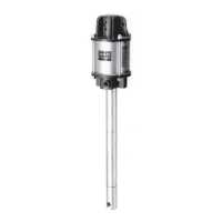
Secure the lower pump assembly in a vise, clamping on flats of the pump body.

Remove Foot Valve Seat

Securely hold suction tube and unthread and remove foot valve seat.

Remove Ball Stop Pin

Remove ball stop pin, releasing the ball.

Remove Suction Tube

Unthread and remove suction tube and washer from pump body.

Push Piston Rod Out

Push piston rod and components out through the bottom end of pump body.

Remove Inner Check Seat Components

Unthread and remove inner check seat, releasing ball, washer, and cup.

Remove Spacer Tube and Solvent Cup

Unthread and remove spacer tube and solvent cup from pump body.

Remove O-Ring and Solvent Cup

Unthread and remove solvent cup from spacer tube and remove O-ring.

Separate Piston Rods

Unthread piston rod from piston rod.

Remove Cup Follower

Loosen nut and unthread and remove cup follower from piston rod.

LOWER PUMP END ASSEMBLY

Assemble O-Ring and Solvent Cup

Assemble O-ring to groove in spacer tube and solvent cup to spacer tube.

Assemble Washers, Packings, Spring

Assemble washers, packing washers, V-packings, and spring into spacer tube.

Assemble Spacer Tube into Pump Body

Assemble washer, spacer tube and components into pump body without tightening.

Slide Piston Rod into Assembly

Slide piston rod into spacer tube and pump body, avoiding damage to V-packings.

Assemble Nut to Piston Rod

Assemble nut to piston rod and thread until 15/32" of threads protrude.

Assemble Cup Follower

Thread cup follower onto piston rod until it contacts nut; tighten nut.

Assemble Cup, Washer, Ball to Follower

Assemble cup, washer, ball to cup follower, securing with inner check seat.

Assemble Washer into Pump Body

Assemble washer into pump body.

Apply Threadlocker to Piston Rod

Apply Loctite 242 Threadlocker to piston rod threads and thread into piston rod.

Assemble Suction Tube

Assemble suction tube to pump body, being careful not to damage cup.

Assemble O-Ring to Foot Valve Seat

Assemble O-ring to groove in foot valve seat.

Assemble Ball and Stop Pin

Assemble ball to foot valve seat, securing with ball stop pin.

Assemble Foot Valve Seat to Tube

Assemble foot valve seat and components to suction tube and tighten.

Tighten Spacer Tube

Tighten spacer tube to pump body.

TROUBLE SHOOTING

Material Leakage Out of Solvent Cup

Material leakage from solvent cup due to worn packings.

Material in One Stroke (Fast Upstroke)

Ball may not be seating on inner check seat; clean or replace.

Material in One Stroke (Fast Downstroke)

Ball may not be seating on foot valve seat or suction inlet restriction.

PARTS LIST AND SPECIFICATIONS

Torque Requirements

Specific torque values for critical components during assembly.

Lubrication and Sealants

Instructions for applying lubricants and sealants during assembly.

Related product manuals