PowerMaster II RF Wattmeter www.arraysolutions.com Rev 4.1 - February 23, 2017
UNPACKING AND SETUP
INITIAL SETUP
Unpack the PowerMaster II. The package should contain:
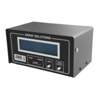
One Power Master II Display – Black enclosure
RF Coupler – Gold colored box with connectors (3 kW or 10 kW) [VHF couplers are different]
– 6 feet long (attached to VHF/UHF)
– 6 feet long (We recommend using a separate PS for this cable, not your TXCVR’s)
This Manual
Please note that we do not ship a software CD ROM with the PowerMaster II. Please go to the Array Solutions website and download the latest
version of the software for your PowerMaster II. .
If anything is missing, give us a call and we'll remedy the problem.
The PowerMaster consists of two major components: The Display and the RF Coupler. The RF Coupler is installed between the output of your
transmitter and your antenna (or antenna tuner input). A six-foot (1.8m) cable is provided for connection between the Display and the Directional
Coupler. You may use a longer cable if you wish (consult the Special Applications section later in this manual).
The PowerMaster uses a standard 2.1mm coaxial power plug, center pin is + V.
Make sure your power source can supply at least 500 mA of current. (800 mA min for the original Power Master)
Please do not use a cheap “wall wart”. These devices are usually not regulated and may cause RFI.