Latched Output: The input signal is directed to a SRQ block and is kept active
until the Reset signal is received. This reset signal is applied by the user to a
SRQ free input; the RESET signal is usually the one selected for this but any
available flag can be used as well.
Inactive: If this option is selected, the LED is considered to be inactive and then
no signal can be assigned to it. Used for internal tests.
Available signals: The set of available signals. They are listed at the end of the
chapter.
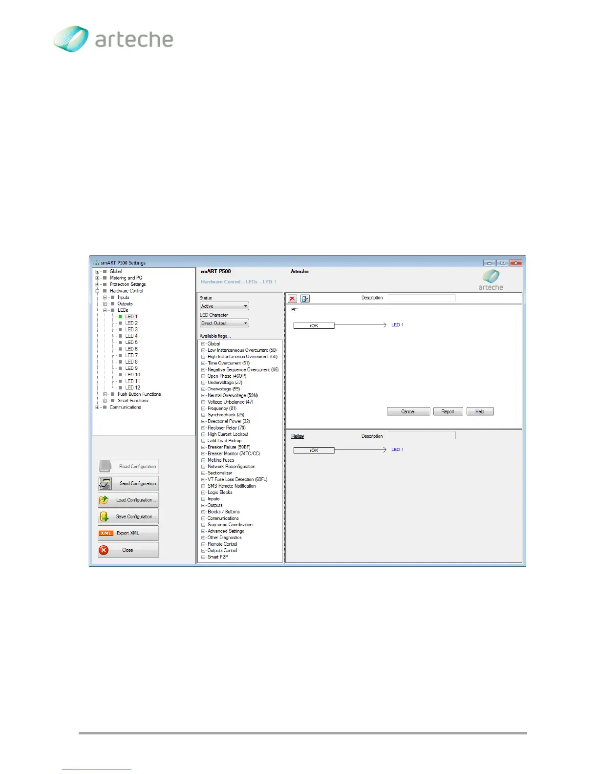
Figure 3-68 LEDs programming
3.5.4. PUSH BUTON PROGRAMMING
The push buttons configuration is very similar to the inputs configuration and the LEDs
programming. The status and the associated signal can be configured for each push