Aruba 9240 Gateway | Installation Guide 9240 Gateway | 7
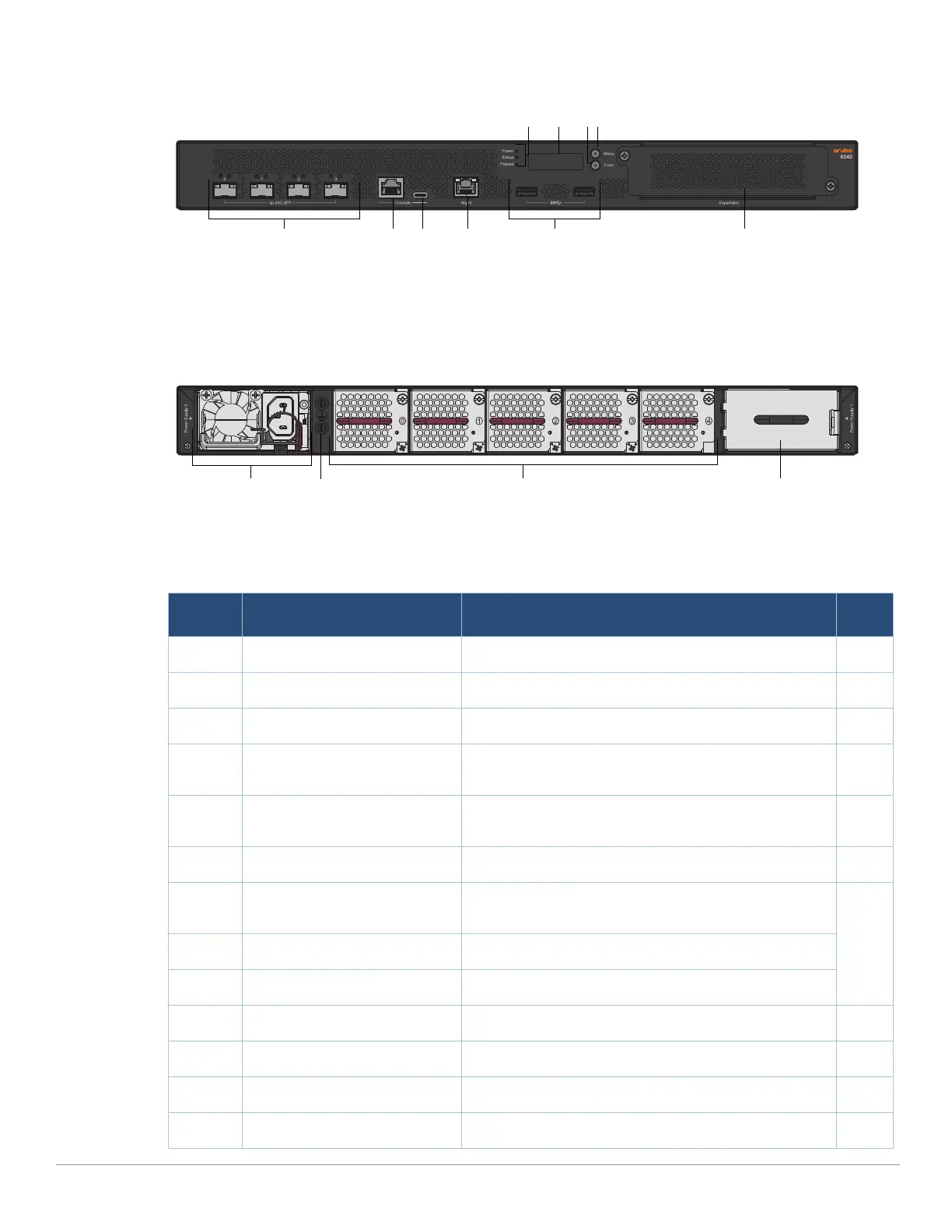
Figure 1 Front Panel of the 9240
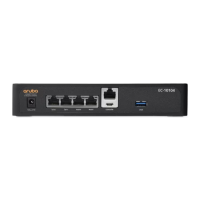
Figure 2 Rear Panel
The following table lists the components on the Aruba 9240 gateway:
Table 3 Aruba 9240 Gateway Components
Callout Component Description Page
1 SFP28 Ports 4 x SFP28 1G/10G/25G data ports 8
2 RJ-45 Console Port RJ-45 serial console access port 11
3 USB Type-C Console Port Provides console access for direct local access 11
4 Management Port An out of band management port (RJ-45), used to
connect to a separate management network
12
5 USB3.0 Interfaces 2 x USB3.0 interfaces. USB storage device can be used
to save and upload configurations
12
6 Power, Status, and Peered LEDs Used for basic monitoring of the Aruba 9240 gateway 9
7 LCD Used to configure LED behavior and other basic
operations
9
8 Enter Button Used to execute actions on the LCD screen
9 Menu Button Used to select the LCD screen menu
10 Expansion Slot Reserved for future use 12
11 PSU Slot 0 Primary power supply module 13
12 Grounding Points Used to attach the grounding screws 12
13 Fans 5 x hot-swappable high speed fans 13