Do you have a question about the AS MOTOR AS 1040 YAK 4WD and is the answer not in the manual?
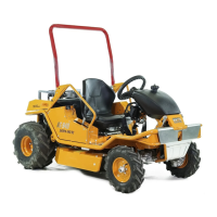
| Brand | AS MOTOR |
|---|---|
| Model | AS 1040 YAK 4WD |
| Category | Lawn Mower |
| Language | English |
General safety instructions for operating and maintaining the mower.
Importance of using genuine AS-MOTOR spare parts for safety and warranty.
Information on using the online portal for parts, drawings, and technical data.
Essential guidelines for maintaining and cleaning the machine for optimal function and lifespan.
Instructions on how to clean the mower thoroughly after each use.
Checklist for visual inspection to ensure safe operation of the machine.
Detailed specifications and technical data for the AS 1040 YAK 4WD mower.
Schedule of regular maintenance tasks, intervals, and required actions.
Importance and guidelines for maintaining correct tyre pressure for optimal performance and safety.
Table detailing tyre sizes, recommended and maximum air pressures for the model.
Specifications for tightening torques of wheel bolts and screws.
General guidelines and torque values for standard bolted connections.
Common faults, their possible causes, and recommended remedies.
Identification and location of key individual engine components.
Procedures for adjusting and regulating engine RPM and idle speed.
Diagram illustrating the force transmission path within the drive system.
Visual guide showing the arrangement and routing of drive belts.
Details on belt tensioners for the transmission and reduction gearing.
Diagram showing the positional layout of major drive components.
First part of the procedure for removing mower unit V-belts.
Continuation of V-belt replacement, including installation.
Initial steps for replacing the flail shaft bearing.
Final steps for replacing the flail shaft bearing.
First part of the procedure for removing the flail shaft.
Second part of the procedure for removing the flail shaft.
First part of the procedure for removing the entire flail mower unit.
Second part of the procedure for removing the flail mower unit.
Final part of the procedure for removing the flail mower unit.
Description of specific improvements or new features in the flail mower unit.
Diagram illustrating the force transmission path within the flail mower unit.
Diagram showing the positional layout of major components in the flail unit.
First part of the procedure for replacing the belt drive for the hydrostatic transmission.
Second part of the procedure for replacing the V-belt of the reduction gearing.
Instructions for changing the hydrostatic oil, including component identification.
Further steps for hydrostatic oil change, including axle procedures and oil heating.
Diagram showing the location and arrangement of the drive lever.
Details on how friction discs hold the drive lever and brake adjustment.
Illustrative view of the hydraulic system from underneath the machine.
Schematic diagram of the hydraulic system with component labels and lines.
Instructions for the correct installation of hydraulic lines to the transmission and front axle.
Explanation of the axle drive function and components, including front axle steering.
Visual guide showing the steering column lever's position within the toothed segment.
Procedure for adjusting the differential, ensuring vertical lever alignment.
Explanation of the front axle damper's function in stabilizing the machine.
Instructions for adjusting the differential cable and brake lever for proper operation.
Details on the adjustment screw for the seat springs.
Explanation of the belt tensioner's structure and moving parts.
Identification and layout of the mower's wiring harness and components.
Comprehensive electrical circuit diagram of the mower.
Location of various electrical components like switches, fuses, and regulators.
Location of central connector and starter relay, with notes on bearing damage.